Brake actuation mechanism employing center valve piston
A technology for actuators and valve pistons, applied in brakes, brake transmissions, transportation and packaging, etc., can solve the problem of increasing the hardware cost of brake actuators and ECUs, reducing pressure estimation accuracy and control quality, and large vibration shocks of motor materials And other problems, to achieve the effect of shortening the braking distance of the car, continuous controllable braking hydraulic pressure, and low cost
- Summary
- Abstract
- Description
- Claims
- Application Information
AI Technical Summary
Problems solved by technology
Method used
Image

Examples
Embodiment 1
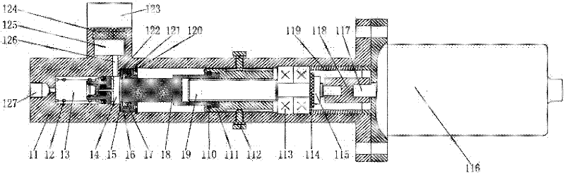
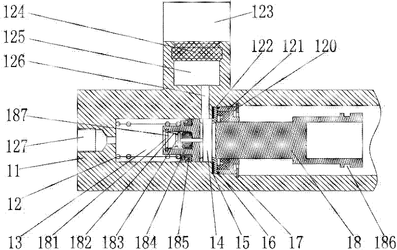
[0025] The overall structure of this embodiment, such as figure 1 As shown, it includes a housing 11, a central valve piston with a control pin hole, a piston driver, a DC motor 116, and an oil pot 123 with a sealing ring 124; the housing 11 includes a right end face with a central hole, The stepped hole and oil storage chamber 125 formed in the housing 11 are composed of left, middle and right round holes; the central valve piston is placed in the left round hole and the middle round hole of the housing, and the piston driving device is placed in the middle and right In the round hole; the left end of the center valve piston and the left round hole form a brake oil chamber 13, and the right end of the center valve piston is connected with the piston driving device, and the piston driving device is connected with the DC motor 116 installed on the right end surface of the housing 11 , the oil pot 123 with sealing ring 124 is installed in the mounting hole processed on the outsi...
Embodiment 2
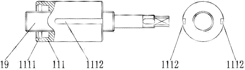
[0035] The structure of this embodiment, such as Figure 4 , Figure 5 As shown, the difference between this embodiment and the specific implementation of embodiment 1 is that the constraining structure used to prevent the rotation of the nut is different, so the housing 21 and nut 211 used are also slightly different from the housing 11 and nut 111 in embodiment 1. There are different. Specifically, this embodiment cancels the anti-rotation constraining structure of the anti-rotation screw 112 and nut anti-rotation groove 1112 in Embodiment 1, but processes two symmetrical planes on the outer surface of the nut 211. On the inner wall of the housing 21 where the two symmetrical planes are located, two corresponding planes are also processed (for example, milled out or cast out), and the planes on the inner wall of the housing 21 match the planes of the nut 211 to form the housing 21 inner wall and the contact plane 212 of the nut 211, thereby preventing the rotation of the n...
Embodiment 3
[0037] The structure of this embodiment, such as Figure 6 As shown, the difference between this embodiment and Embodiment 1 is that the snap ring, the piston snap ring groove and the nut snap ring groove are canceled, and the piston body 38 and the nut 311 are no longer connected by the snap ring in Embodiment 1, but The connection between the two is realized through the interference fit between the piston body 38 and the nut 311 . The interference fit between the piston body 38 and the nut 311 is realized by a cold packing process: the piston body 38 is dropped into a coolant (such as liquid nitrogen) for a certain period of time to shrink the radial dimension of the piston body 38, and then the piston body 38 is The body 38 is inserted into the nut 311, and when the piston body 38 returns to its original radial dimension as the temperature rises, the piston body 38 and the nut 311 achieve an interference fit, and the two are connected. Of course, other suitable methods such ...
PUM
 Abstract
Description
Claims
Application Information
 - R&D
- Intellectual Property
- Life Sciences
- Materials
- Tech Scout
- Unparalleled Data Quality
- Higher Quality Content
- 60% Fewer Hallucinations
Browse by: Latest US Patents, China's latest patents, Technical Efficacy Thesaurus, Application Domain, Technology Topic, Popular Technical Reports.
© 2025 PatSnap. All rights reserved.Legal|Privacy policy|Modern Slavery Act Transparency Statement|Sitemap|About US| Contact US: help@patsnap.com