Supercharge Your Innovation With Domain-Expert AI Agents!

Coded lock permanent magnet assembly locking device

A technology of permanent magnets and lockers, which is applied in the application of electromagnets, building locks, locks, etc., can solve the problems of high power consumption of electromagnetic coils, easy jamming of iron rod support spring 5, and impact on safety, etc., to achieve Improve the safety and reliability level, eliminate the hidden danger of illegal unlocking, and prolong the effect of battery life

Inactive Publication Date: 2011-11-02
NINGBO YONGFA GROUP
View PDF8 Cites 9 Cited by
  • Summary
  • Abstract
  • Description
  • Claims
  • Application Information

AI Technical Summary

Problems solved by technology

[0004] The iron rod 4 is normally supported by the iron rod and the spring 5 bounces up elastically. The iron rod 4 is easily shaken up and down by external force vibration. When the iron rod shakes downward, there is a hidden danger of illegal unlocking, which affects safety. Once it loses its elasticity or is easy to get stuck and rust, it will affect the normal work
When unlocking, the magnetic field force of the electromagnetic coil must make the iron rod overcome the elastic support of the supporting spring, and consume enough energy, so that the electromagnetic coil consumes a lot of power, the working life of the battery is short, and the reliability is poor.

Method used


Image

  • Coded lock permanent magnet assembly locking device
  • Coded lock permanent magnet assembly locking device
  • Coded lock permanent magnet assembly locking device

Examples


Embodiment Construction

[0014] The structure and working process of the present invention will be further described below in conjunction with the accompanying drawings.

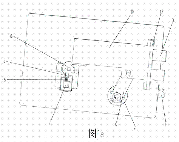
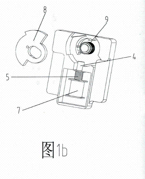
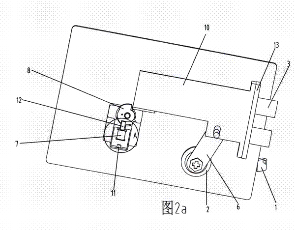
[0015] see Figure 2a , Figure 2b with Figure 2c As shown, the mechanical parts of the electronic combination lock include a key 1 , a lock cylinder 2 , a lock cylinder bolt connecting rod 6 , a cam block 8 , a deadbolt linkage 10 , and a deadbolt 3 . Figure 2a Indicates the back of the lockset, the lower end of the lock cylinder and bolt connecting rod 6 is connected to the lock cylinder 2, and the upper end is connected to the bolt linkage 10, the bolt 3 at the front end of the bolt linkage 10 passes through the locking frame 13, and the bolt linkage The lower part of the rear end of 10 is arranged to be in contact with the vertical plane of the upper end of the cam block 8. The permanent magnet assembly is arranged under the cam block 8, including the electromagnetic coil 7, and the permanent magnet rod 12 arranged in the mi...


PUM


Abstract

The invention relates to a coded lock permanent magnet assembly locking device. The coded lock permanent magnet assembly locking device comprises a lock core, a lock bolt, a lock core and lock bolt connecting member, a lock bolt linkage member, a cam dog, a CPU (Central Processing Unit) circuit, a key input and a display screen and is characterized in that an electromagnetic coil mutually connected with an output end of a CPU is arranged below the cam dog; a permanent magnet rod is arranged in the electromagnetic coil; a permanent magnet block is arranged at the bottom of the electromagnetic coil; the permanent magnet rod and the permanent magnet block generate forces with repellent magnetic fields to drive the permanent magnet rod to ascend; the upper end of the permanent magnet rod is in movable contact with the lower end face of the cam dog; and the upper end face of the cam dog and the rear end of the lock bolt linkage member are locked closely. According to the invention, instead of an iron rod, a strong magnetic neodymium iron boron permanent magnet block arranged at the bottom of the coil is used for supporting a spring to work so that the hidden trouble of illegal unlocking is eliminated and the safety and reliability level is increased; and a strong magnetic neodymium iron boron permanent magnet rod is adopted instead of the ordinary iron rod, so that the energy consumption is reduced, the miniaturization can be realized, working current of a working current coil can be reduced to one third less than the original working current, and then the battery service life is prolonged.

Description

technical field [0001] The invention relates to an electromechanical integrated lock, in particular to an electromechanical integrated password lock using a permanent magnet assembly as a locking device. Background technique [0002] my country updated the national standard GB10409-2001 on anti-theft safes in 2001. So far, the locks of electronic combination lock safes have not changed significantly. Locking devices for safes, safes and gun safes are now standard on every electronic safe, safe and gun safe. [0003] Shown in Fig. 1 is the structural diagram of the conventional electromagnet control unlocking of password safe on the market, Figure 1b for Figure 1a The return spring 9 enlarged and hidden under the cam block 8 includes an unlocking key 1, a mechanical lock cylinder 2, a lock tongue 3, an iron rod 4, an iron rod support spring 5, a lock cylinder lock tongue connector 6, and an electromagnet coil 7. Cam block 8, return spring 9, deadbolt linkage 10, etc. Norm...

Claims


Application Information

Patent Timeline
Patent Type & Authority Applications(China)
IPC IPC(8): E05B47/06E05B49/00E05B65/52H01F7/18
Inventor 蔡海善
Owner NINGBO YONGFA GROUP
Features
  • R&D
  • Intellectual Property
  • Life Sciences
  • Materials
  • Tech Scout
  • Unparalleled Data Quality
  • Higher Quality Content
  • 60% Fewer Hallucinations
Learn More