Parameterized sizing method for turbine blade mould cavity

A turbine blade, parametric technology, used in electrical digital data processing, special data processing applications, instruments, etc., can solve the problems of long cycle, low efficiency and low precision, and achieve short design cycle, high efficiency and high precision. Effect

Active Publication Date: 2011-11-02
NORTHWESTERN POLYTECHNICAL UNIV
View PDF2 Cites 26 Cited by
  • Summary
  • Abstract
  • Description
  • Claims
  • Application Information

AI Technical Summary

Problems solved by technology

[0007] In order to overcome the deficiencies of the prior art, the present invention provides a method for designing the cavity of precision casting molds based on geometric characteristic parameters. The design re...

Method used


Image

  • Parameterized sizing method for turbine blade mould cavity
  • Parameterized sizing method for turbine blade mould cavity
  • Parameterized sizing method for turbine blade mould cavity

Examples


Embodiment Construction

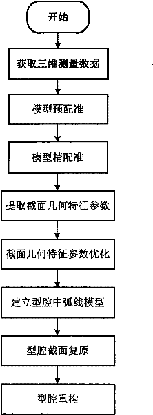
[0047] The design of the cavity of the shaping mold for producing a certain type of aviation turbine blade, the embodiment steps are as follows figure 1Shown:

[0048] step 1

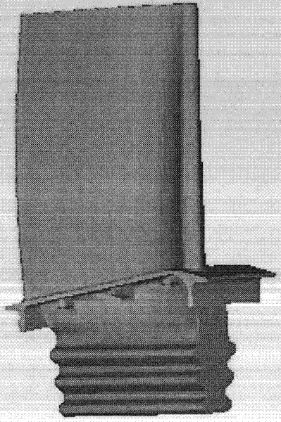
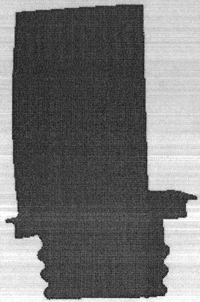
[0049] Use UG software (commercial software name, German Siemens product) to read in the CAD model and measurement model of a certain type of aeroengine turbine blade, the CAD model is as follows figure 2 , the measurement model as image 3 .

[0050] step 2

[0051] Pre-register the measurement model with the CAD model, and the pre-registration results are as follows Figure 4 .

[0052] step 3

[0053] Accurately register the measurement model and the CAD model, and the registration results are as follows: Figure 5 .

[0054] step 4

[0055] Take the precisely aligned CAD model and the measurement model along the Z direction of the blade height direction, intercept a section at a height of Z=50mm, and extract the geometric characteristic parameters of the CAD model and the measurement mode...


PUM


Abstract

The invention discloses a parameterized sizing method for a turbine blade mould cavity. The parameterized sizing method comprises the following steps of: measuring an existing turbine blade to obtain a measurement model; performing registering positioning and precise registering on a computer-aided design (CAD) model and the corresponding measurement model to obtain geometric characteristic parameters of two-dimensional sections of the measurement model and the CAD model on the same height and calculating deformation vectors of the two-dimensional sections; conversely adjusting the deformation vectors and representing a middle arc model of a blade shape by using a cubic polynomial curve; then restoring the mould cavity; and repeatedly establishing at least four blade shape sections of the mould cavity at any height and finally reconstructing an entity of the mould cavity. By the parameterized sizing method, the product yield of the turbine blades is increased greatly and the period and the frequency of mould trail are reduced; and the parameterized sizing method has the characteristics of short design period, high precision and high efficiency.

Description

technical field [0001] The invention relates to the technical field of mold cavity shaping, in particular to a parametric shaping method for an aeroengine turbine blade mold cavity. Background technique [0002] Turbine blades are the core technology of high thrust-to-weight ratio engines, the core components of turbomachinery, and also vulnerable to failure. Its performance level, especially its ability to withstand high temperatures, is an important symbol of the advanced level of a type of engine, and in a certain sense, it is also a significant symbol of the level of a country's aviation industry. Due to the long-term service under the conditions of strong thermal shock and complex cyclic thermal stress, the structural design and manufacturing technology of turbine blades have become the core technology of high thrust-to-weight ratio aeroengines. [0003] At present, turbine blades generally adopt directional crystallization or single crystal precision casting without m...

Claims


Application Information

Patent Timeline
IPC IPC(8): G06F17/50
Inventor 卜昆张定华董一巍程云勇黄魁东窦杨青窦杨柳张现东刘金钢杨小宁袁帅傅蒋威周丽敏乔燕张亮
Owner NORTHWESTERN POLYTECHNICAL UNIV
Why Eureka
Try Eureka