Strapdown inertial navigation device based on micro mechanical gyroscopes

A strapdown inertial navigation and micro-mechanical gyroscope technology, applied in the field of strapdown inertial navigation systems, can solve the problems of not meeting the needs of miniaturization, high price, and large volume of mechanical gyroscopes, so as to ensure simplicity, stability, and measurement Effects of precision and design, volume and mass reduction

Inactive Publication Date: 2011-11-09
BEIHANG UNIV
View PDF3 Cites 10 Cited by
  • Summary
  • Abstract
  • Description
  • Claims
  • Application Information

AI Technical Summary

Problems solved by technology

[0003] Modern applications are increasingly emphasizing the low cost and small size of products, which puts forward higher requirements for inertial navigation devices. Traditional inertial navigation devices mostly use mechanical inertial devices. Among them, platform inertial navigation devices are large in size, heavy in weight, and expensive. Expensive; the relatively mature mechanical gyro strapdown inertial navigation device can not meet the miniaturization requirements due to the large size of the traditional mechanical gyroscope; at present, the laser gyro strapdown inertial navigation device and fiber optic gyro inertial There are also problems of large volume and heavy weight, which cannot meet the needs of miniaturization
Therefore, the above traditional inertial navigation devices and the existing laser gyro and fiber optic gyro inertial navigation devices cannot meet the requirements of modern applications for low cost and miniaturization of products.

Method used


Image

  • Strapdown inertial navigation device based on micro mechanical gyroscopes
  • Strapdown inertial navigation device based on micro mechanical gyroscopes
  • Strapdown inertial navigation device based on micro mechanical gyroscopes

Examples


Embodiment Construction

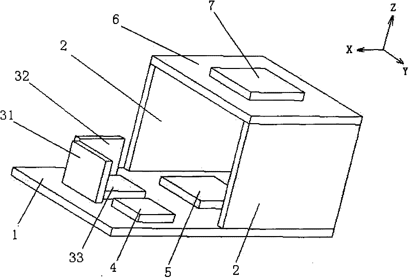
[0017] Such as figure 1 As shown, the present invention is a small-volume strapdown inertial navigation device based on a micro-mechanical gyroscope and a three-axis semiconductor micro-accelerometer. The specific embodiments of the present invention are described below in conjunction with the accompanying drawings.

[0018] see figure 1 As shown, the present invention consists of a signal acquisition circuit 1, a link pin header 2, an X-axis micro-mechanical gyroscope 31, a Y-axis micro-mechanical gyroscope 32, a Z-axis micro-mechanical gyroscope 33, a three-axis semiconductor micro-accelerometer 4, a signal acquisition chip 5, The data processing circuit 6 and the data processing chip 7 are composed. The signal acquisition circuit 1 and the data processing circuit 6 are stacked and fixedly connected through pin headers, forming the basic mechanical skeleton of the strapdown inertial navigation system. The X-axis micromechanical gyroscope 31 is fixed on the signal acquisit...


PUM


Abstract

The invention discloses a strapdown inertial navigation device based on micro mechanical gyroscopes, comprising three micro mechanical gyroscopes, a triaxial semiconductor micro accelerometer, a signal pickup chip, a signal pickup circuit, a data processing chip and a data processing circuit. The signal pickup circuit and the data processing circuit constitute a base mechanical skeleton. The X-axis mechanical gyroscope is fixed on the signal pickup circuit, and the Y-axis mechanical gyroscope and Z -axis mechanical gyroscope are fixed on the signal pickup circuit vertically. The data processing chip is fixed on the data processing circuit, and the triaxial semiconductor micro accelerometer and the signal pickup chip are both fixed on the signal pickup circuit. By using three small-sized micro mechanical gyroscopes and the triaxial semiconductor micro accelerometer as inertial sensing elements, the volume of the inertial measuring device is reduced, the measuring accuracy is guaranteed, and the cost is reduced. By the reasonable structural design, the space is utilized effectively, and the volume and quality of the system are further reduced. The strapdown inertial navigation device based on micro mechanical gyroscopes has the advantages of small volume, light weight, simple structure, impact resistance, low cost and the like, and is capable of being used in the fields of aerospace and the like.

Description

Technical field [0001] The invention relates to a strapdown inertial navigation system based on a micro-mechanical gyroscope and a semiconductor micro-accelerometer, which can be used to measure the rotational angular velocity and acceleration of a carrier, and can calculate the attitude and position of the carrier through a corresponding algorithm, especially a A small-volume, low-cost strapdown inertial navigation system. Background technique [0002] An inertial navigation system (INS) is an autonomous navigation system. It relies on measuring the acceleration and angular velocity of the carrier itself (missile, car, aircraft, etc.) to calculate the instantaneous velocity, position, and heading attitude of the carrier. Therefore, the inertial devices that make up the inertial navigation system are all installed inside the carrier, and do not rely on any external information or radiate energy when working. Therefore, the inertial navigation system has good concealment, s...

Claims


Application Information

Patent Timeline
Patent Type & Authority Applications(China)
IPC IPC(8): G01C21/16
Inventor 丑武胜丁俐丁文武
Owner BEIHANG UNIV
Why Eureka
Try Eureka