
Automatic wire arranging and winding machine

An automatic wire arrangement and winding machine technology, which is applied in coil manufacturing, electrical components, and delivery of filamentous materials, etc., can solve the problems of wires affecting quality, lack of insulation of inductance coils, and complex structures, etc., to achieve convenient and flexible operation, insulation Good effect and smooth transmission

Inactive Publication Date: 2011-11-09
上海通力电工设备厂
View PDF0 Cites 17 Cited by
  • Summary
  • Abstract
  • Description
  • Claims
  • Application Information

AI Technical Summary

Problems solved by technology

But it has the following disadvantages: the winding speed is pre-set by the program, and cannot be changed during the winding process, which is inconvenient to operate; two-way winding is realized by setting two sets of winding mechanisms, not only the structure is complicated, but also the repeated bending of the wire affects the quality ;The synchronous action between the host and the pay-off mechanism is difficult, and it is prone to loose wires or motor stalled operation; the use of wires and insulating paper to wind together can achieve insulation effects, but the two sides of the inductance coil lack insulation

Method used


Image

  • Automatic wire arranging and winding machine
  • Automatic wire arranging and winding machine
  • Automatic wire arranging and winding machine

Examples


Embodiment Construction

[0021] In order to make the technical means, creative features, goals and effects achieved by the present invention easy to understand, the present invention will be further described below in conjunction with specific diagrams.

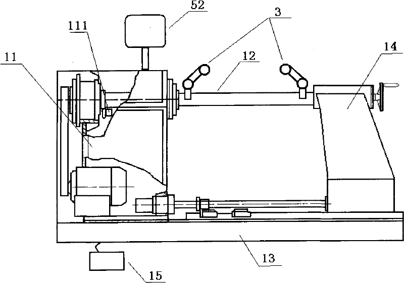
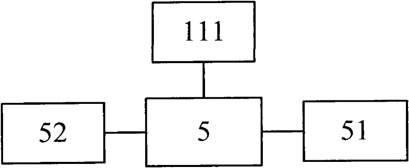
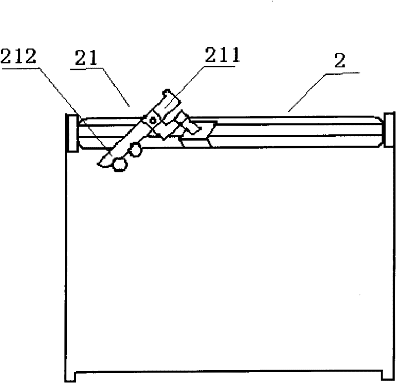
[0022] refer to figure 1 , figure 2 , image 3 , Figure 4 , automatic cable winding machine, including a host, a cable mechanism 2, a pay-off mechanism, an insulating paper winding system, the host includes a main shaft box 11, a main shaft 12, a machine base 13, a tailstock 14, and an electric power supply The unit, the insulating paper winding system includes a layer of insulating paper winding system, one end insulating paper winding system, the layer insulating paper winding system includes a support for placing layers of insulating paper and the layer winding power system, the layer winding power system includes a layer for paper feeding Paper loading system, layer paper cutting system for paper cutting, the layer paper cutting system is pr...


PUM


Abstract

The invention relates to the field of machining, in particular to an automatic wire arranging and winding machine. The automatic wire arranging and winding machine comprises a main machine, a wire arranging mechanism, a paying-off mechanism, an insulated paper winding system and a motor set for providing power, wherein the insulated paper winding system comprises a layer insulating paper winding system and an end insulating paper winding system; the layer insulating paper winding system comprises a bracket and a layer winding power system; the layer winding power system comprises a layer paper feeding system and a layer paper shearing system; the end insulating paper winding system comprises a paper tray and an end winding action system; the end winding action system comprises an end paper feeding system and an end paper shearing system; the end paper feeding system is provided with a paper pressing roller; the motor controlled input end of the paper pressing roller is connected with a micro controller system; and the circumferential surface of the paper pressing roller is provided with a concave cavity capable of accommodating a coil lead. Because the technical scheme is adopted, the automatic wire arranging and winding machine realizes the automatic wire winding function, the transmission of the whole machine is stable, and a coil manufactured by the automatic wire arranging and winding machine has a good insulating effect.

Description

technical field [0001] The invention relates to the field of mechanical processing, in particular to a winding machine. Background technique [0002] Transformer is a commonly used equipment. In the current transformer production, the coil of the transformer is made of enamelled copper wire (referred to as enameled wire) and other wires to form an inductance coil. A winding machine is required to wind the inductance coil. The overall structure of the existing transformer coil winding machine is generally made up of main engine, wire arrangement mechanism, wire payout mechanism, insulating paper winding mechanism and computer control system. Under the control of the computer program, the main engine can start and stop slowly, run at a constant speed, evenly and precisely arrange the wires, and wind in the forward and reverse directions; The insulating paper winding mechanism has the function of placing insulating paper. But it has the following disadvantages: the winding sp...

Claims


Application Information

Patent Timeline
Patent Type & Authority Applications(China)
IPC IPC(8): H01F41/12H01F41/06B65H54/04H01F41/079H01F41/096
Inventor 顾伟顾华平
Owner 上海通力电工设备厂
Learn More