Design method for main runner of fuel cell stack and fuel cell stack structure

A fuel cell stack and fuel cell unit technology, which is applied to fuel cell components, fuel cells, fuel cell grouping, etc., can solve problems such as the inability to achieve the best power generation efficiency, the difficulty in shunting fuel gas, and the difficulty in controlling power generation conditions.

Inactive Publication Date: 2011-11-09
CHUNG HSIN ELECTRIC & MACHINERY MFG
View PDF0 Cites 2 Cited by
  • Summary
  • Abstract
  • Description
  • Claims
  • Application Information

AI Technical Summary

Problems solved by technology

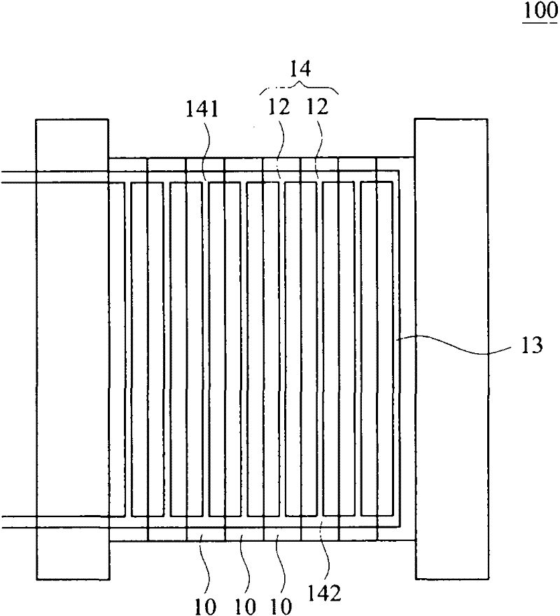
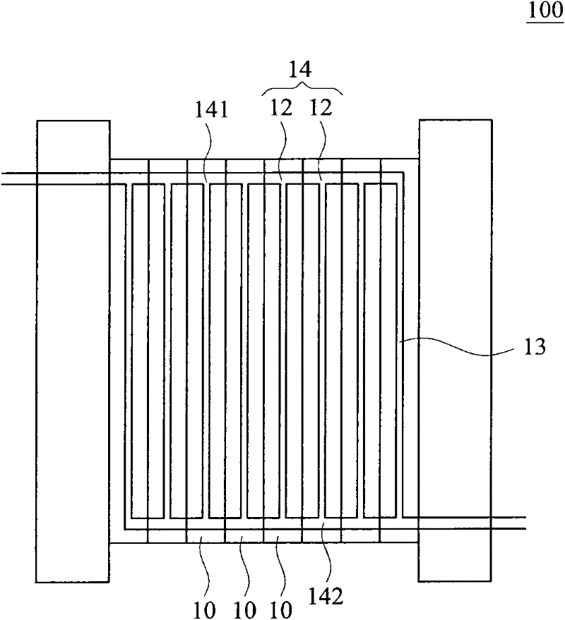
[0006] However, no matter what type of main channel 14 it is, it is difficult for the fuel gas to be evenly divided into each fuel cell unit 10. In the case of a fixed width of the main channel 14, the head and tail of the main channel 14 in the fuel cell stack 100 The flow rate of the flow channels 13 at both ends is mostly the smallest, and the flow rate of the flow channel 13 in the middle is large, so that each fuel cell unit 10 cannot achieve the best power generation efficiency. Secondly, the power generation status of each fuel cell unit 10 is independent and difficult to control. Many variables cannot be known by simulation, so if the power generation efficiency of each fuel cell unit 10 can be improved separately, the overall efficiency of the fuel cell stack 100 can be improved.
[0007] It can be seen that the above-mentioned existing method for designing the main channel of the fuel cell stack obviously still has inconvenience and defects in method and use, and needs to be further improved urgently.
In order to solve the above-mentioned problems, the relevant manufacturers have tried their best to find a solution, but no suitable design has been developed for a long time, and the general method has no suitable method to solve the above-mentioned problems. This is obviously related. The problem that the industry is eager to solve

Method used


Image

  • Design method for main runner of fuel cell stack and fuel cell stack structure
  • Design method for main runner of fuel cell stack and fuel cell stack structure
  • Design method for main runner of fuel cell stack and fuel cell stack structure

Examples


Embodiment Construction

[0038] In order to further explain the technical means and effects of the present invention to achieve the intended purpose of the invention, the method for designing the main channel of the fuel cell stack and the structure of the fuel cell stack according to the present invention will be described in detail below in conjunction with the accompanying drawings and preferred embodiments. Embodiments, methods, steps, features and effects thereof are described in detail below.

[0039] The aforementioned and other technical contents, features and effects of the present invention will be clearly presented in the following detailed description of preferred embodiments with reference to the drawings. Through the description of the specific implementation mode, when the technical means and functions adopted by the present invention to achieve the predetermined purpose can be obtained a deeper and more specific understanding, but the accompanying drawings are only for reference and des...


PUM


Abstract

The invention relates to a design method for the main runner of a fuel cell stack and a fuel cell stack structure. The method comprises the following steps: providing a fuel cell stack, and obtaining a design for a main runner, wherein the fuel cell stack is formed by stacking multiple fuel cell units and runners of the fuel cell units are stacked to form the main runner as well. Through setting control devices at one side of each runner and independently controlling the position of each control device in the runner, the widths of the runners and the flows of the fuel gases in the runners can be further controlled, so that the bypass flow of the fuel gases in the fuel cell stack can be uniform and the generating efficiency of the fuel cell stack can be further improved. Besides, a curve structure of the width of the main runner is designed for the main runner.

Description

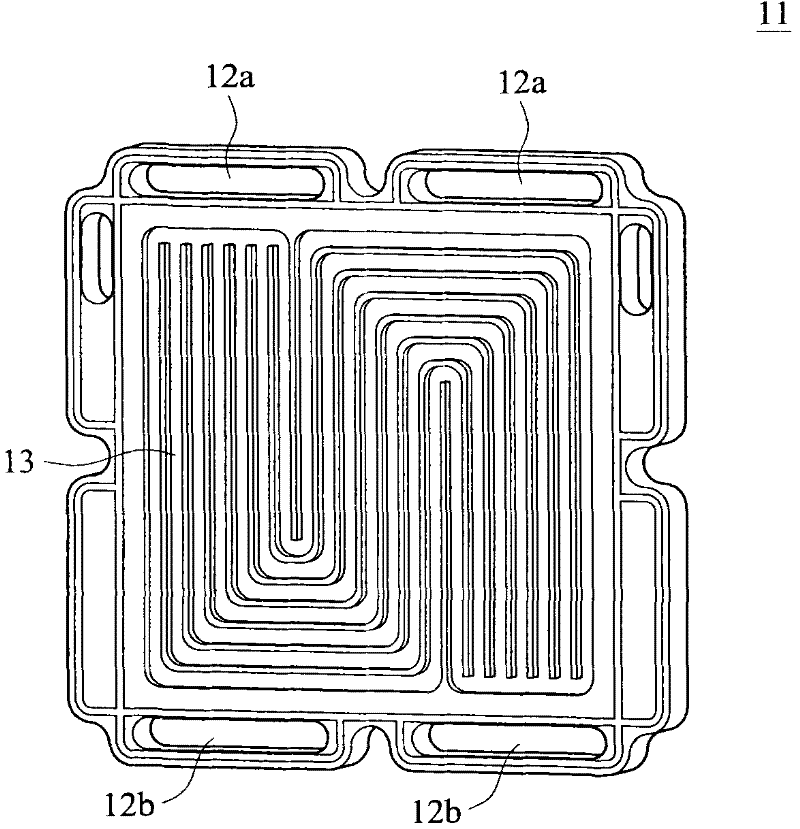
technical field [0001] The invention relates to a method for designing a fuel cell stack main channel and its fuel cell stack structure, in particular to a method for designing a fuel cell stack main channel and its fuel cell stack structure applied to the fuel cell stack structure design. Background technique [0002] A fuel cell uses hydrogen and oxygen as reactants to generate electricity through a series of electrochemical reactions, and its products are only electricity, waste heat and pure water, so it is a relatively environmentally friendly power generation device. In addition, due to the low voltage and low current of a single fuel cell unit, it cannot be used alone. Therefore, multiple fuel cell units are stacked and connected in series to form a fuel cell stack to provide a more compact structure and facilitate product design. [0003] figure 1 It is a schematic diagram of a flow field plate 11 of a conventional fuel cell stack. Figure 2A It is a schematic diag...

Claims


Application Information

Patent Timeline
Patent Type & Authority Applications(China)
IPC IPC(8): H01M8/24H01M8/02H01M8/0258H01M8/2483
CPCY02E60/50
Inventor 周泊贤吴启斌
Owner CHUNG HSIN ELECTRIC & MACHINERY MFG
Why Eureka
Try Eureka