Active device tracking using light with orbital angular momentum to induce a hyperpolarized mri

A technology of orbital angular momentum and generating device, which is applied in the field of tracking technology, can solve inaccurate problems and achieve the effect of improving accuracy

Inactive Publication Date: 2011-11-09
KONINKLIJKE PHILIPS ELECTRONICS NV
View PDF3 Cites 4 Cited by
  • Summary
  • Abstract
  • Description
  • Claims
  • Application Information

AI Technical Summary

Problems solved by technology

These indirect methods have drawbacks, such as being inaccurate in situations where the instrument is not rigid, the line of sight between the light emitter and the electronics is obstructed by the surgeon or other equipment in the room, and the like
Additionally, the technique is susceptible to inaccuracies from nearby metallic objects that can distort the field and from the highly magnetic environment found inside MRI scanners

Method used


Image

  • Active device tracking using light with orbital angular momentum to induce a hyperpolarized mri
  • Active device tracking using light with orbital angular momentum to induce a hyperpolarized mri
  • Active device tracking using light with orbital angular momentum to induce a hyperpolarized mri

Examples


Embodiment Construction

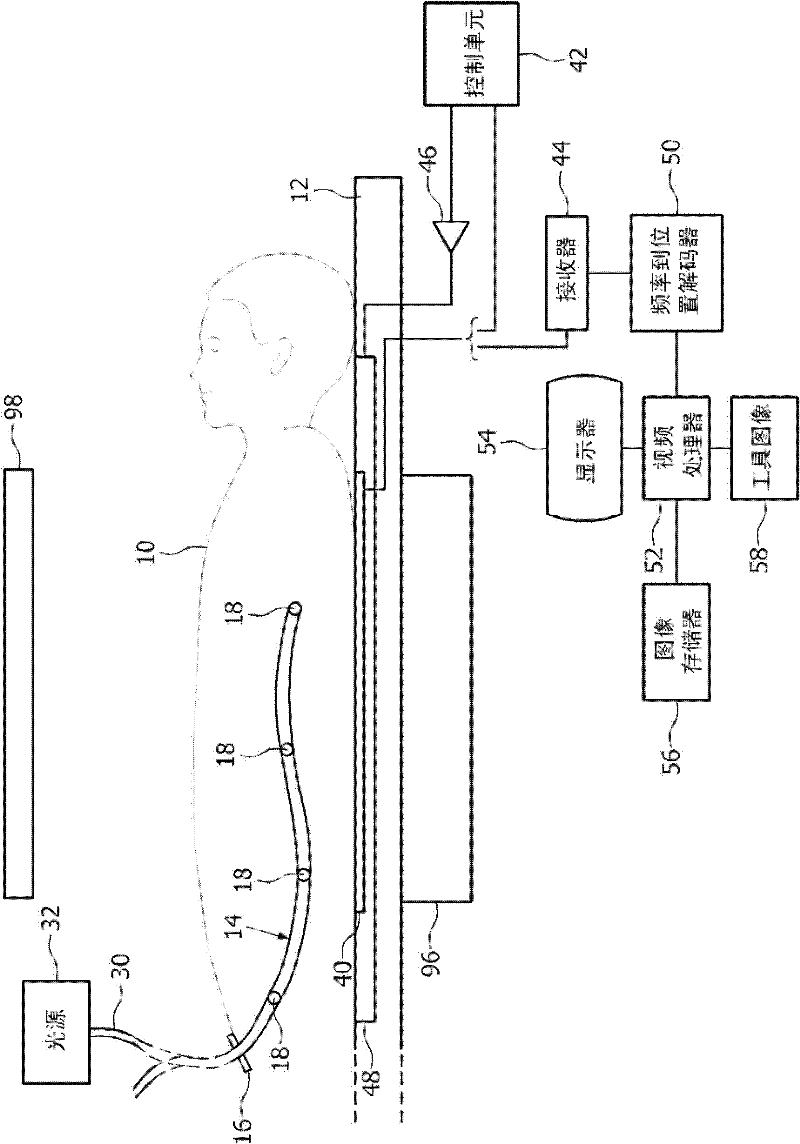
[0021] refer to figure 1 , placing the patient 10 on the support surface 12 in preparation for the minimally invasive surgical procedure. A minimally invasive surgical device such as catheter 14 is inserted into the patient through an orifice 16 in, for example, the femoral artery. At one or more known locations along the catheter, for example near the tip, means 18 for generating a beam of orbital angular momentum are provided. For example, when inserting a stent or performing balloon angioplasty, a balloon catheter is typically inserted through port 16 and fed along the patient's arterial system to the site of the blockage. As the catheter is moved through the arterial system, the catheter is tracked to mark its position. A guide wire or other navigation system is used to direct the tip of the catheter along the appropriate branch to bring the tip to the location of the blockage using the arterial system in a manner similar to the highway system.

[0022] continue to refe...


PUM


Abstract

One or more light beam endowed with photonic orbital angular momentum generating devices (18) are mounted at preselected locations on an insertable instrument (14) to hyperpolarize nuclear magnetic dipoles in a region of interest (80). The hyperpolarized nuclear magnetic dipoles are caused to resonate, generating magnetic resonance signals. A controller (42) controls gradient coils to induce a magnetic field gradient across the region of interest, such that the frequency of the resonance signals is indicative of spatial position. A frequency-to-position decoder (50) converts the resonance signal frequencies into spatial positions. A video processor (52) combines the spatial positions and a portion of a diagnostic image from a diagnostic image memory (56) into a combined display which depicts the location of the region of interest or a portion of the instrument marked on the diagnostic image and displays the combined image on a monitor (54).

Description

technical field [0001] This application relates to tracking technology. It finds particular application in image-guided minimally invasive surgical procedures and will be described in this application with specific reference thereto. However, the present application can also be applied in conjunction with the positioning of other instrumented targets. Background technique [0002] When performing minimally invasive image-guided surgery, the surgeon is often unable to see the surgical field and the working ends of surgical instruments. Rather, the surgeon "sees" the surgical field via the diagnostic images. In order for these minimally invasive surgical systems to function as intended, the surgeon must understand where the working end of the surgical instrument is located relative to the target tissue and diagnostic images within the patient's surgical field. [0003] Mechanical tracking systems rigidly fix surgical tools to a stationary reference plane such as an operatin...

Claims


Application Information

Patent Timeline
Patent Type & Authority Applications(China)
IPC IPC(8): A61B19/00A61B5/055A61B5/06
CPCA61B2019/5231A61B5/055A61B2019/5236A61B5/06A61B19/5244A61B2019/5251A61B34/20A61B2034/2051A61B2090/373A61B2090/374
Inventor D·R·埃尔戈特L·R·阿尔布
Owner KONINKLIJKE PHILIPS ELECTRONICS NV
Why Eureka
Try Eureka