Thermo-electric pile infrared detector

An infrared detector and thermopile technology, applied in the field of infrared detectors, can solve the problems of reduced absorption efficiency, reduced response rate, reduced infrared absorption area, etc., to achieve the effects of improved sensitivity, improved response rate, and improved temperature difference

Active Publication Date: 2011-11-16
INST OF MICROELECTRONICS CHINESE ACAD OF SCI
View PDF5 Cites 21 Cited by
  • Summary
  • Abstract
  • Description
  • Claims
  • Application Information

AI Technical Summary

Problems solved by technology

Among them, the thermopile infrared detector has many advantages and is widely used. The thermopile infrared detector is an uncooled infrared detector based on the Seebeck effect. With the development of Electro Mechanical systems), thermopile infrared detectors based on micromachines are also widely used. At present, for micromechanical thermopile types, the main types of thermocouples are: P-type polysilicon and gold thermocouples, Si epitaxial layer P-type Diffusion area and aluminum thermocouple, N-type polysilicon and P-type polysilicon thermocouple, and use silicon oxide-silicon nitride composite dielectric layer as the infrared absorption layer. Compared with other detectors, this micromechanical thermopile infrared detector has high Sensitivity, relaxed working environment and very wide spectral response, and compatible with standard IC technology, low cost and suitable for mass production, but with the reduction of pixel size, the infrared absorption area also decreases, resulting in absorption efficiency decrease, and the response rate also decreases

Method used


Image

  • Thermo-electric pile infrared detector
  • Thermo-electric pile infrared detector
  • Thermo-electric pile infrared detector

Examples


Embodiment Construction

[0012] The following disclosure provides many different embodiments or examples for implementing different structures of the present invention. To simplify the disclosure of the present invention, components and arrangements of specific examples are described below. Of course, they are only examples and are not intended to limit the invention. Furthermore, the present invention may repeat reference numerals and / or letters in different instances. This repetition is for the purpose of simplicity and clarity and does not in itself indicate a relationship between the various embodiments and / or arrangements discussed. In addition, various specific process and material examples are provided herein, but one of ordinary skill in the art will recognize the applicability of other processes and / or the use of other materials. Additionally, configurations described below in which a first feature is "on" a second feature may include embodiments where the first and second features are form...


PUM


Abstract

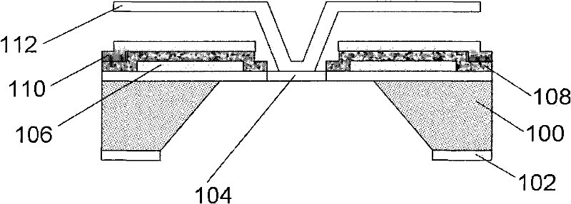
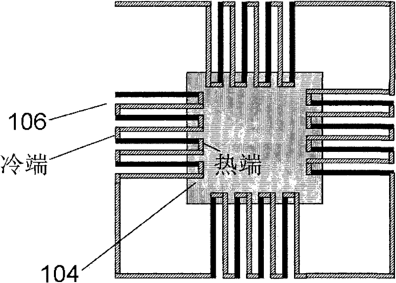
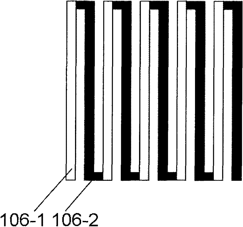
The invention relates to a thermo-electric pile infrared detector, which comprises a substrate with a full-hollow structure, a thermo-electric pile, a first infrared absorption layer, a passivation layer, a reflective layer and a second infrared absorption layer formed by the release technology of a sacrifice layer, wherein the thermo-electric pile, the first infrared absorption layer and the passivation layer are formed on the substrate; and the reflective layer is formed on the passivation layer. By the detector, the infrared absorptivity is improved, and temperature difference of a thermoelectric couple at a cold end and a hot end is increased, so the response rate and sensitivity of the detector are improved.

Description

technical field [0001] The present invention generally relates to the field of infrared detectors, in particular to a thermopile infrared detector based on a micro-electromechanical system. Background technique [0002] At present, the use of infrared technology for infrared temperature measurement, infrared alarm, infrared detection, infrared tracking, etc., is widely used in various fields such as military, industry, medicine, agriculture and forestry, environmental protection, fire protection, search and rescue, etc. Among them, the thermopile infrared detector has many advantages and is widely used. The thermopile infrared detector is an uncooled infrared detector based on the Seebeck effect. With the development of Electro Mechanical systems), thermopile infrared detectors based on micromachines are also widely used. At present, for micromechanical thermopile types, the main types of thermocouples are: P-type polysilicon and gold thermocouples, Si epitaxial layer P-type...

Claims


Application Information

Patent Timeline
Patent Type & Authority Applications(China)
IPC IPC(8): H01L35/32H01L35/02
Inventor 刘瑞文焦斌斌陈大鹏
Owner INST OF MICROELECTRONICS CHINESE ACAD OF SCI
Why Eureka
Try Eureka