Reflection gain type high-power laser device

A high-power laser, reflection gain technology, applied in the field of lasers, can solve the problems of concentration quenching, difficulty in ensuring uniformity, and difficulty in increasing the upper limit of laser power, and achieve the effect of high output power upper limit and increased energy density

Inactive Publication Date: 2011-11-16
BEIJING JIAOTONG UNIV
View PDF0 Cites 2 Cited by
  • Summary
  • Abstract
  • Description
  • Claims
  • Application Information

AI Technical Summary

Problems solved by technology

When the gas density increases, the intensity of backscattering will increase, which will affect the gain of the laser; and the practice of increasing the doping concentration of the gain medium in the solid is difficult to ensure the uniformity of the concentration, such as doping rare earth ions In...

Method used


Image

  • Reflection gain type high-power laser device
  • Reflection gain type high-power laser device
  • Reflection gain type high-power laser device

Examples


Embodiment approach 1

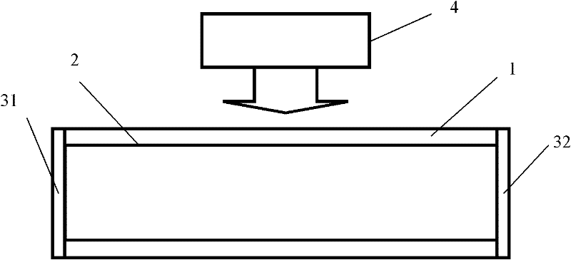
[0022] A reflective gain type high-power laser, the laser includes a quartz tube 1 , a gain coating 2 on the inner wall of the tube, a total reflection mirror 31 , a partial reflection mirror 32 , and a pump source 4 .

[0023] The material of the gain coating 2 on the inner wall of the tube is ytterbium ion, and the thickness of the gain coating 2 on the inner wall of the tube is 10 nm.

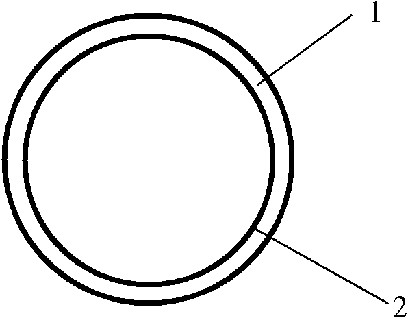
[0024] The cross-sectional shape of the quartz tube 1 is that the inner and outer walls are circular, such as figure 1 , 2 shown.

[0025] The gain coating 2 on the inner wall of the tube totally reflects the generated laser signal.

[0026] The total reflection mirror 31 totally reflects the generated laser signal.

[0027] The reflectivity of the partial reflector 32 to the generated laser signal is 4%.

[0028] The pumping source 4 directly irradiates the quartz tube 1 from the side, and the direct irradiation means that the pump light generated by the pumping source 4 enters the quar...

Embodiment approach 2

[0030] The difference between Embodiment 2 and Embodiment 1:

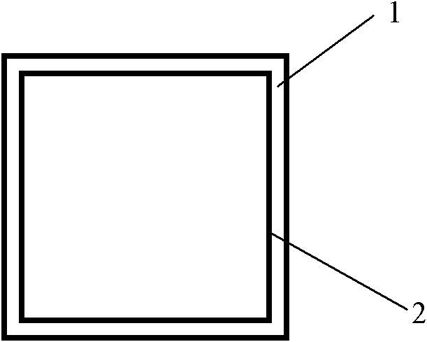
[0031] The inner and outer walls of the cross-sectional shape of the quartz tube 1 are rectangular, such as image 3 shown.

[0032] The material of the gain coating 2 on the inner wall of the tube is erbium ion, and the thickness of the gain coating 2 on the inner wall of the tube is 30nm.

[0033] The reflectivity of the partial reflector 32 to the generated laser signal is 96%.

Embodiment approach 3

[0035] The difference between Embodiment 3 and Embodiment 1:

[0036] The inner wall of the cross-sectional shape of the quartz tube 1 is star-shaped, and the outer wall is circular, such as Figure 4 shown.

[0037] The material of the gain coating 2 on the inner wall of the tube is neodymium ion, and the thickness of the gain coating 2 on the inner wall of the tube is 60nm.

[0038] The reflectivity of the partial reflector 32 to the generated laser signal is 50%.


PUM

PropertyMeasurementUnit
Thicknessaaaaaaaaaa
Thicknessaaaaaaaaaa
Thicknessaaaaaaaaaa

Abstract

The invention discloses a reflection gain type high-power laser device and relates to the fields such as industrial cutting, military science and the like with higher requirements on the power of the laser device. The laser device comprises a quartz tube (1), an internal tube wall gain coating (2), a totally reflecting mirror (31), a partially reflecting mirror (32) and a pumping source (4); and the internal tube wall gain coating (2) is made from rare earth ions. The internal tube wall gain coating (2) can be used for totally reflecting generated laser signals. The totally reflecting mirror (31) can be used for totally reflecting the generated laser signals. The reflectivity of the partially reflecting mirror (32) to the generated laser signals is 4-96%. The pumping source (4) can be used for directly irradiating the quartz tube (1) from the lateral side. The shape of the cross section of the quartz tube (1) is characterized in that both the internal wall and the external wall are circular or rectangular, or the internal wall is star-shaped and the external wall is circular. The reflection gain type high-power laser device disclosed by the invention is beneficial to solving of the problem of concentration quenching resulting from overhigh doped concentration in the high-power rare earth ion doped laser device.

Description

technical field [0001] The invention relates to a laser, which is especially used in fields such as industrial cutting and military affairs which have higher requirements on the power of the laser. Background technique [0002] The production and development of lasers have made outstanding contributions to the improvement of national life, and their application fields are far wider than originally imagined. Nowadays, due to the increasing importance of lasers, people pay more and more attention to them, so the funds, manpower and material resources invested in the research and development of lasers are increasing day by day. The special structure of the laser can make the output laser have good directionality and high energy density. At present, most of the gain methods of lasers are that the laser propagates in the growth medium, and the laser gain is doubled by exciting the excited state particles in the gain medium each time. This method can produce a good output effect...

Claims


Application Information

Patent Timeline
IPC IPC(8): H01S3/03
Inventor 温晓东宁提纲裴丽李晶周倩油海东
Owner BEIJING JIAOTONG UNIV
Why Eureka
Try Eureka