Device and method for detecting discharge state in electric spark linear cutting work gap

A discharge state and cutting processing technology, which is applied in the field of detection devices for gap discharge state in wire electric discharge cutting, can solve problems such as inability to process, increase feed speed, and high average voltage, and achieve good real-time performance, wide application range, and convenient operation Effect

Inactive Publication Date: 2011-11-23
HARBIN INST OF TECH
View PDF5 Cites 27 Cited by
  • Summary
  • Abstract
  • Description
  • Claims
  • Application Information

AI Technical Summary

Problems solved by technology

This gap state detection method can approximately reflect the current gap discharge state, but since the gap average voltage is composed of the average voltage of various discharge states, it cannot detect a single pulse discharge state, so the average voltage method contains uncertain factors. Real-time and accurate monitoring of the gap cannot be realized, which may deteriorate the processing effect
Especially for wire electric discharge machining of insulating ceramics, due to the existence of high-resistance discharge state, the average voltage of the gap is high, and the average voltage detection method will speed up the feed speed, which will cause the processing effect to deteriorate or even fail to process. At this time, the average voltage Detection method failure

Method used


Image

  • Device and method for detecting discharge state in electric spark linear cutting work gap
  • Device and method for detecting discharge state in electric spark linear cutting work gap
  • Device and method for detecting discharge state in electric spark linear cutting work gap

Examples


Embodiment 1

[0041] The wire electric discharge machining of embodiment 1 metal material

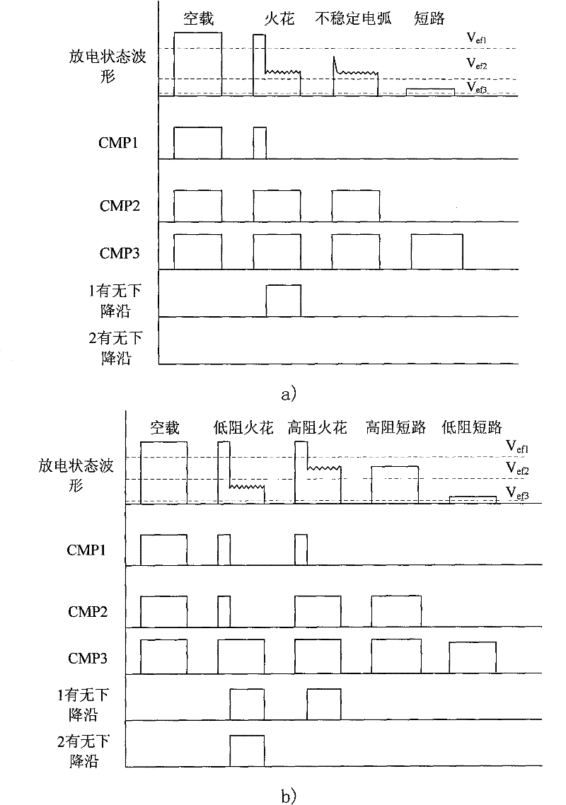
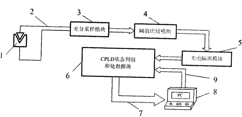
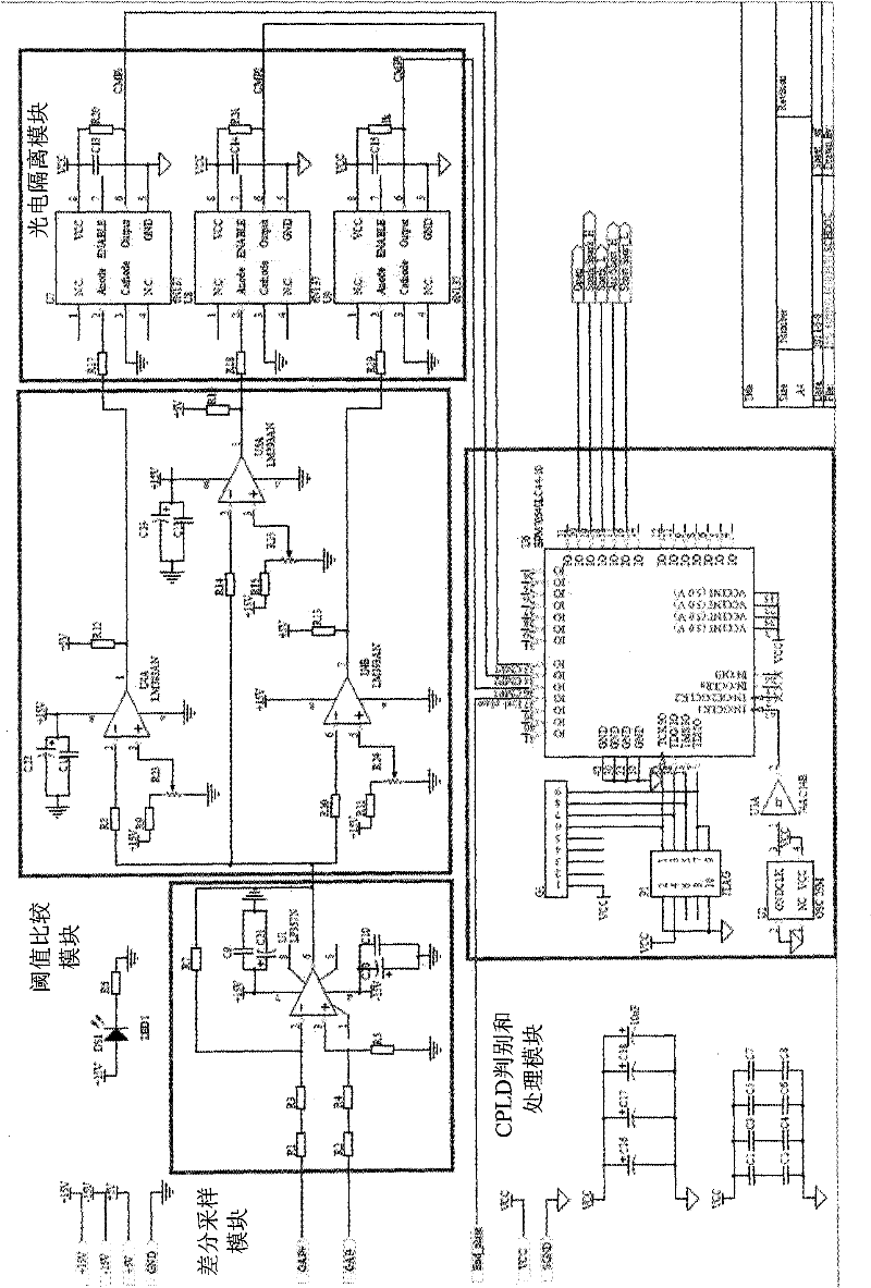
[0042] Hardware circuit and CPLD internal circuit such as Figure 2-5 mentioned, only need to adjust V ef1 , V ef2 , V ef3 Three thresholds are enough. The corresponding threshold setting value is relative to the no-load voltage, and the threshold setting of the three comparators of the threshold comparison module corresponds to the threshold V ef1 , V ef2 , V ef3 , but its value is equal to V ef1 , V ef2 , V ef3 Multiplied by the sampling scale of the differential sampling block. Threshold V ef3 It is set to 3~5V. Its function is to distinguish the pulse width and pulse interval of each pulse. The control detection program only judges the discharge state during the pulse width, and does not judge the state during the pulse interval to prevent misjudgment. Threshold V ef2 Set to be slightly less than the metal pulse discharge sustain voltage value, the threshold V ef1 Set slightly below ...

Embodiment 2

[0045] Embodiment 2 Wire-cut electric discharge machining of insulating ceramic material

[0046] Hardware circuit and CPLD internal circuit such as Figure 2-5 mentioned, only need to adjust the threshold V ef2 That's it. Threshold V ef2 It is set to be slightly larger than the metal pulse discharge sustaining voltage value, so in the WEDM of insulating ceramics, V ef3 set to 3V, V ef2 Set to 40V. V ef1 Set to 70V.

[0047] The gap voltage enters the threshold comparison module through the differential sampling module, and compares it with the set threshold. After photoelectric isolation, the waveforms of the CMP1, CMP2, and CMP3 signals, as well as the outputs of the CPLD internal breakdown signal detection modules Inst1 and Inst33, such as figure 1 b) as shown.

[0048] During the high level period of CMP3, that is, the pulse width period, different gap discharge states have different CMP1 and CMP2 signals. During the pulse width, if the output of CMP1 and CMP2 has...


PUM


Abstract

The invention relates to a device and a method for detecting the discharge state in an electric spark linear cutting work gap, and belongs to the technical field of electric spark machining. A differential sampling module of the device is connected with the two poles of an electric spark machine tool through a signal transmission cable; a signal output end of the differential sampling module is connected with a signal input end of a threshold value comparison module; a signal output end of the threshold value comparison module is connected with a signal input end of a photoelectric isolation module; a first signal input end of a complex programmable logic device (CPLD) state distinguishing and processing module is connected with a signal output end of the photoelectric isolation module; and a signal output end of the upper computer is connected with a second signal input end of the CPLD state distinguishing and processing module through a CPLD program downloading cable. The threshold value comparison module compares sampled gap voltage signals with set three threshold values through an integration comparator, and sends the comparison result to the photoelectric isolation module. The device and the method can be used for detecting the pulse discharge state of the gap in the electric spark linear cutting machine tool.

Description

Technical field: [0001] 本发明涉及一种电火花线切割加工间隙放电状态检测装置与方法,属于电火花加工技术领域。 Background technique: [0002] 电火花加工是通过工具电极和工件之间脉冲性火花放电来蚀除工件材料,以达到对零件的尺寸、形状及表面质量预定的加工要求。 电火花加工方法不受工件的材料硬度、强度等机械性能的限制,同时具有宏观切削力小等优点,因此特别适合加工难加工材料及复杂形状工件加工,在航空、航天、模具等领域有着广泛 Applications. [0003] 在金属材料的电火花加工过程中,极间电压信号反应了加工过程中脉冲放电情况,这与电火花加工的效率和精度密切相关。当脉冲放电为火花放电状态时,间隙两端电压由空载电压经过一段时间的击穿延时,间隙发生击穿,间隙两端电压由空载电压下降为放电维持电压。在电火花线切割加工中,由于电极丝和工件存在相对运动,一般认为不存在稳定电弧放电现象。但在实际加工过程中,存在没有击穿延时的放电现象,这种放电状态为偏短路的不稳定电弧放电状态。它表明此时间隙排屑困难,加工状态差,所以在电火花线切割加工过程中,需要将这种放电状态和含有击穿延时的火花放电状态区分出来。因此在金属材料的电火花线切割加工中,间隙脉冲放电状态分为:空载,火花放电,不稳定电弧放电和短路。 [0004] 电火花加工技术一般用来加工导电材料,现有的辅助电极法可以实现利用电火花技术加工绝缘陶瓷,其原理是在工件表面附加导电层,利用放电过程中形成的导电膜构成辅助电极实现放电加工。在绝缘陶瓷的电火花线切割加工过程中,当导电膜形成差时,此时导电膜厚度小,电阻大,出 现间隙高电压放电现象。当间隙放电电压高于加工金属时的维持电压,将此时的火花放电状态称为高阻火花状态,此时的短路状态称为高阻短路状态。当导电膜形成良好时,此时导电膜厚度大,电阻小,间隙放电电压近似等于加工金属时的维持电压,将此时的火花放电状态称为低阻火花状态,此时的短路状态称为低阻短路状态。因此,在绝缘陶瓷电火花线切割加工中,间隙放电状态被分为五种,分别是空载、高阻火花、低阻火花、高阻短路和低阻短路状态。 [0005] 目前的电火花线切割加工机床,一般只对间隙的平均电压进行检测,并以此为参考值决定当前伺服进给速度的大小。当间隙平均电压高于...

Claims


Application Information

Patent Timeline
Patent Type & Authority Applications(China)
IPC IPC(8): B23H7/04B23H7/02
Inventor 郭永丰侯朋举郑绍清陈兰
Owner HARBIN INST OF TECH
Why Eureka
Try Eureka