Measuring system of relative position of laser mode and aperture and measuring method thereof

A measurement system and relative position technology, applied in the field of measurement, can solve the problems of unstable beam intensity and shape, fluctuation of image analysis results, unreliable recognition results, etc., and achieve the effects of small imaging error, high-definition shooting, and high resolution

Inactive Publication Date: 2011-11-23
XIDIAN UNIV
View PDF3 Cites 4 Cited by
  • Summary
  • Abstract
  • Description
  • Claims
  • Application Information

AI Technical Summary

Problems solved by technology

The detection method for the relative position of the aperture and the light beam in this document solves the shortcomings of the traditional method of direct detection by the detector, but in this system, the intensity of the light beam observed from the camera cannot be synchronized with the sawtooth wave signal because the camera acquisition cannot With the change of the sawtooth wave signal, it will constantly change between strong and weak, and the obtained beam position will fluctuate greatly due to the continuous change of beam intensity, and the recognition result is very unreliable
Although an image processing algorithm based on statistics is also proposed in this paper to effectively identify the beam, when the beam deviates far from the central axis of the resonator, the intensity and shape of the beam are unstable, and the image analysis results will appear unstable. Large fluctuations affect the measurement accuracy

Method used


Image

  • Measuring system of relative position of laser mode and aperture and measuring method thereof
  • Measuring system of relative position of laser mode and aperture and measuring method thereof
  • Measuring system of relative position of laser mode and aperture and measuring method thereof

Examples


Embodiment Construction

[0028] The following will clearly and completely describe the setting of the optical system, the relative position measurement system of the laser mode and the aperture of the present invention in conjunction with the accompanying drawings, and use the image processing module to process and calculate the detailed process of obtaining the center coordinates of the laser mode and the center coordinates of the aperture .

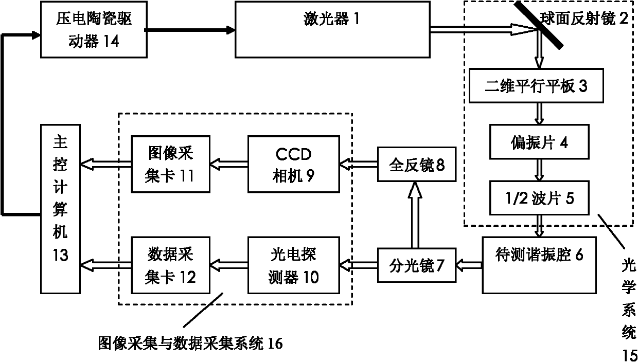
[0029] refer to figure 1 , The measurement system of the present invention includes a laser 1, an optical system 15, a resonant cavity to be measured 6, a beam splitter 7, a total reflection mirror 8, an image acquisition and data acquisition system 16, a main control computer 13 and a piezoelectric ceramic driver 14. in:

[0030] The laser 1 is a single-mode frequency-sweeping laser with piezoelectric ceramics attached to it. By controlling the piezoelectric ceramics, the frequency of the laser output from the laser 1 can be adjusted, and the output laser is ...


PUM


Abstract

The invention discloses a measuring system of relative position of a laser mode and an aperture and a measuring method thereof, and mainly solves the disadvantage of low measurement precision of present systems. The whole system comprises a laser (1), an optical system (15), a resonator to be measured (6), a spectroscope (7), a total reflective mirror (8), an image acquisition and data acquisition system (16), a main control computer (13), and a piezoelectric ceramics driver (14); the piezoelectric ceramics driver drives the laser to output laser; the optical system is adjusted to allow the laser outputted by the laser to be coupled to the resonator to be measured; the laser outputted by the resonator to be measured are divided into two paths by the spectroscope and the total reflective mirror; the two-path laser is collected and transmitted to the main control computer by the image acquisition and data acquisition system; the main control computer processes images of the aperture andthe laser mode by using a high-precision image processing algorithm, and calculates the central coordinates of the aperture and the laser mode respectively. The invention has the advantages of synchronous CCD camera acquisition and sawtooth wave signals, and high measurement precision, and is applicable to the high-precision automatic regulation of the laser.

Description

technical field [0001] The invention belongs to the field of measurement technology, and in particular relates to the measurement of the diaphragm and laser mode in the laser gyroscope resonator cavity, which is used to realize the high-precision automatic cavity adjustment of the laser. Background technique [0002] In the production process of laser gyroscope, the processing and installation errors of optical components such as resonant cavity and lens, as well as the disturbance of ambient temperature and pressure will cause the position and inclination angle of the reflective lens to shift, causing the cavity mirror to be out of adjustment, resulting in laser gyroscope resonance The performance of the cavity decreases, ie the optical losses of the resonator increase. Therefore, in order to minimize the loss of the resonant cavity, it is necessary to tune the resonant cavity. By adjusting the position and inclination angle of the mirror, the above-mentioned errors and dis...

Claims


Application Information

Patent Timeline
Patent Type & Authority Applications(China)
IPC IPC(8): G01C25/00
Inventor 邵晓鹏徐大雍龚昌妹王锐许宏涛范华梁凤明卢光旭董文晓
Owner XIDIAN UNIV
Why Eureka
Try Eureka