
High-precision ceramic substrate process

A ceramic substrate, high-precision technology, used in electrical components, semiconductor/solid-state device manufacturing, circuits, etc., can solve the problems of metal layer peeling, non-stick welding, oxidation, etc., to improve product yield and reduce production costs. Effect

Inactive Publication Date: 2011-11-23
HOLY STONE ENTERPRISE
View PDF0 Cites 7 Cited by
  • Summary
  • Abstract
  • Description
  • Claims
  • Application Information

AI Technical Summary

Problems solved by technology

[0004] However, the raw materials of general ceramic substrates are roughly divided into three types, namely aluminum nitride (AlN), aluminum oxide (Al 2 o 3 ) and low temperature co-fired ceramics (LowTemperature Cofired Ceramics; LTCC), in which aluminum nitride (AlN) is sintered in a vacuum furnace, while alumina (Al 2 o 3 ) and low temperature cofired ceramics (Low Temperature Cofired Ceramics; LTCC) use a general sintering furnace, but because the circuit above the ceramic substrate is sintered with a light cup, the circuit is already formed, and the oxygen in the general sintering furnace will oxidize the circuit. As a result, when soldering or electroplating is performed in the subsequent process, the plated metal layer will peel off or the soldering will not stick, making the product a defective product or a waste product. Generally, manufacturers will be limited by raw materials in the production of optical cups, but Different processes and processing may require the use of different raw materials, which will limit the production and manufacturing. The above-mentioned known ceramic materials have many problems and deficiencies in the process. This is the inventor and those engaged in this industry. The goal of urgent improvement

Method used


Image

  • High-precision ceramic substrate process
  • High-precision ceramic substrate process
  • High-precision ceramic substrate process

Examples


Embodiment Construction

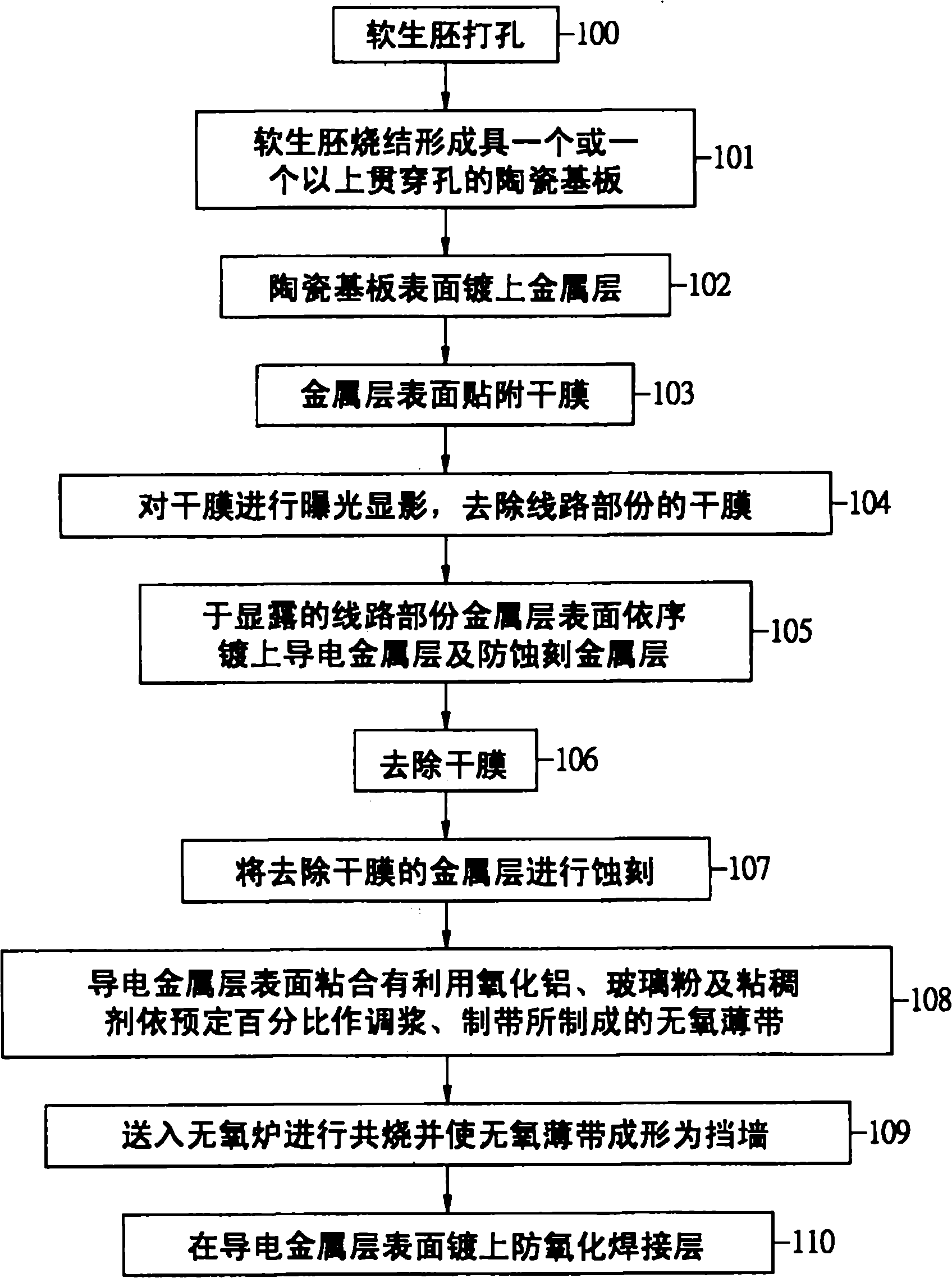
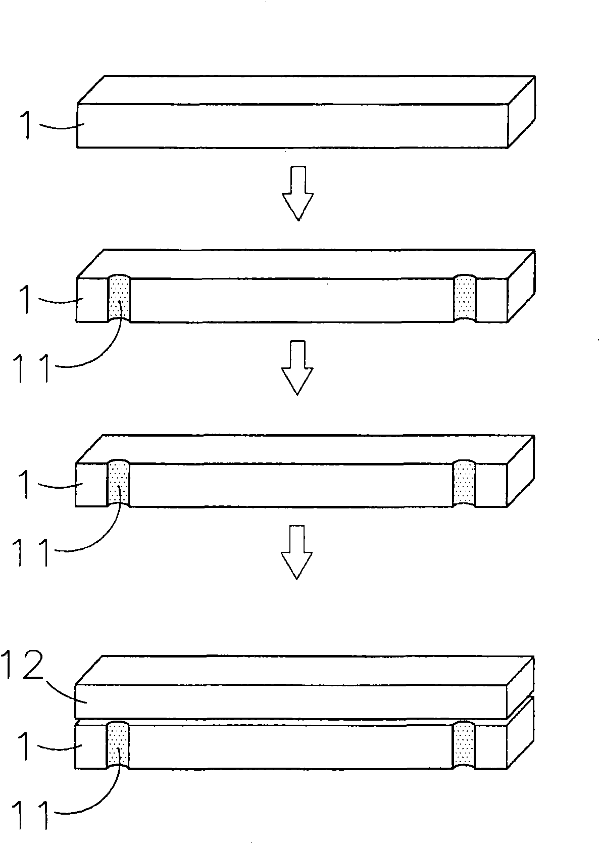
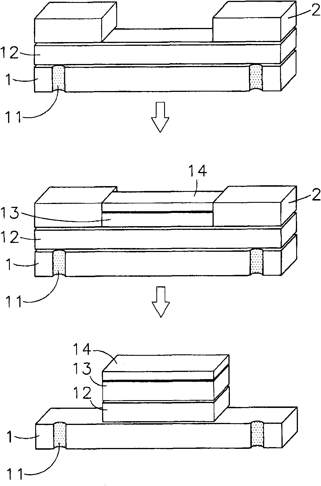
[0036] The surface of the ceramic substrate of the present invention is plated with a metal layer and a conductive metal layer, and after exposure, development, and etching to form a predetermined circuit part, the surface of the conductive metal layer can be bonded with aluminum oxide, glass powder and a viscous agent that can be vacuum sintered. The oxygen-free thin strip is then co-fired in an oxygen-free furnace to form a retaining wall, which can prevent the oxidation of the conductive metal layer and allow the welding and electroplating processes to operate smoothly, thereby avoiding waste and defective products, thereby improving product yield and reduce manufacturing cost.

[0037] In order to understand the above purpose and effects of the present invention, preferred embodiments will be described in detail below in conjunction with the accompanying drawings.

[0038] see figure 1 , 2 , 3, and 4 show the schematic diagram of the steps of the preferred embodiment of ...


PUM


Abstract

The invention discloses a high-precision ceramic substrate process. In the high-precision ceramic substrate process, a ceramic substrate is required to be manufactured in electroplating and high-accuracy exposure / etching ways. Differences from an ordinary ceramic substrate manufactured in a printing way particularly after a metal layer is plated on the surface of the ceramic substrate are that: a dry film is attached to the surface of the metal layer, and is exposed and developed; a conductive metal layer is plated on the exposed surface of the metal layer; the metal layer and the conductive metal layer in a line part are retained by etching; an anaerobic thin strip is adhered to the surface of the conductive metal layer at a preset position, and is made by mixing a preset percent of ceramic powder, a preset percent of glass powder and a preset percent of pasting agent to form size and manufacturing the strip; and the ceramic substrate is fed into an anaerobic furnace for cofiring, and the anaerobic thin strip can form a barricade. The cofiring is performed in the anaerobic furnace, so the conductive metal layer may not be oxidized to overcome the shortcoming of stripping of the plated metal layer or no sticking in welding in subsequent welding and electroplating processes.

Description

technical field [0001] The present invention relates to a high-precision ceramic substrate process, and the high-precision ceramic substrate process must be produced by electroplating and high-precision exposure / etching, which is different from ceramic substrates generally produced by printing, especially the surface of ceramic substrates After the metal layer and the conductive metal layer are plated, the oxygen-free thin tape made of aluminum oxide, glass powder and vacuum sinterable viscous agent according to the predetermined percentage is made into paste, and the tape is bonded on the conductive metal layer, and then sent into the air-free The oxygen furnace is co-fired to form a retaining wall, which can avoid the oxidation of the conductive metal layer, and the subsequent welding and electroplating processes can work smoothly. Background technique [0002] According to, with the rapid development of science and technology and the pursuit of higher quality of life by h...

Claims


Application Information

Patent Timeline
IPC IPC(8): H01L21/48H01L33/62H01L33/64
Inventor 林文新
Owner HOLY STONE ENTERPRISE
Learn More