Riverside tail water treatment system device

A technology of treatment system and water distribution device, applied in water/sewage multi-stage treatment, water/sludge/sewage treatment, chemical instruments and methods, etc. Difficulties, interception and reduction of emission pollutants, etc.

Inactive Publication Date: 2011-11-30
HOHAI UNIV
View PDF6 Cites 2 Cited by
  • Summary
  • Abstract
  • Description
  • Claims
  • Application Information

AI Technical Summary

Problems solved by technology

[0005] At present, there is insufficient research on the impact of the tail water discharged from the sewage plant on the ecological environment of the landscape river and how to further intercept and reduce the discharge of pollutants before the tail water of the sewage plant completely enters the urban landscape river.
Most tail water advan

Method used


Image

  • Riverside tail water treatment system device
  • Riverside tail water treatment system device
  • Riverside tail water treatment system device

Examples


Embodiment 1

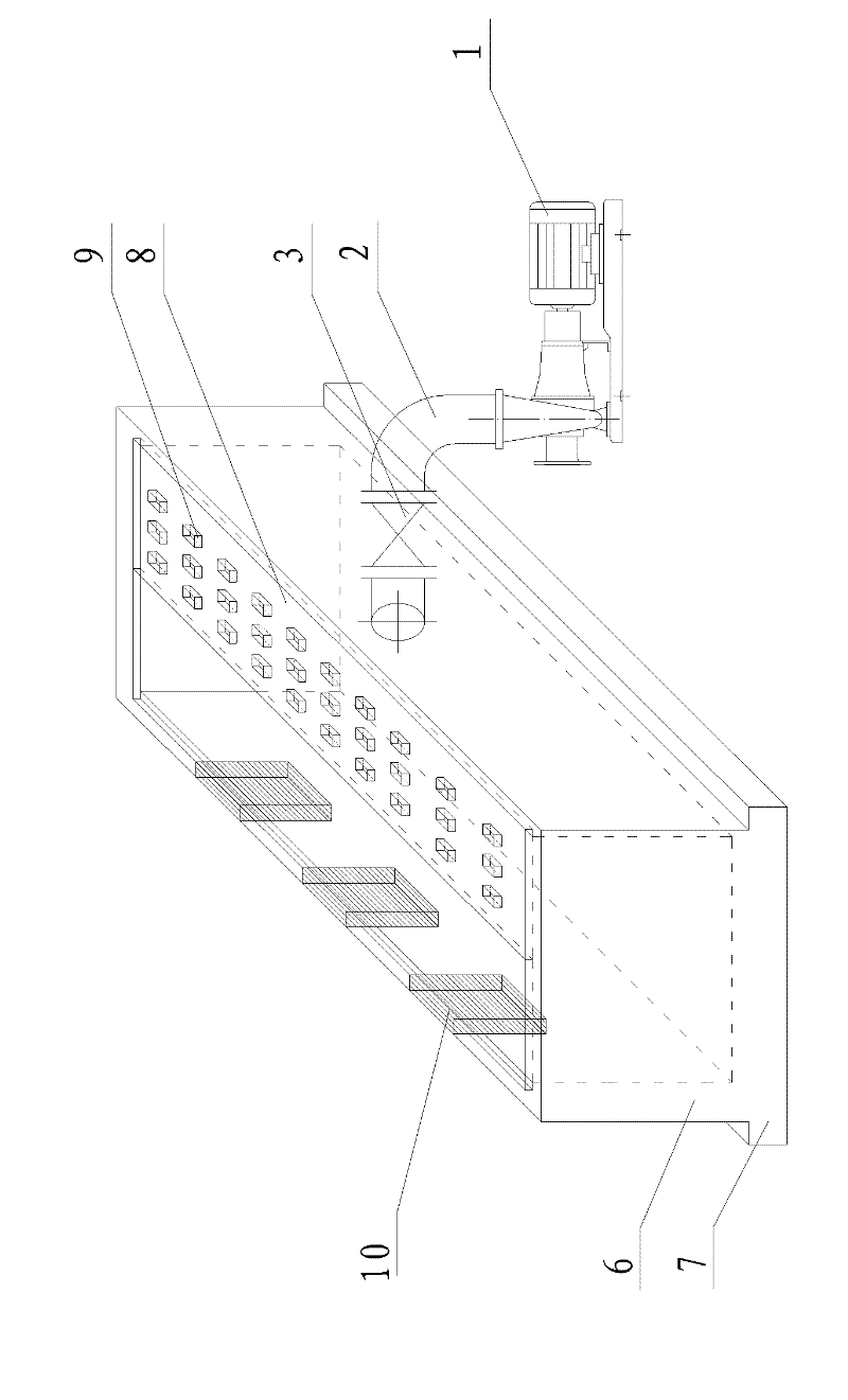
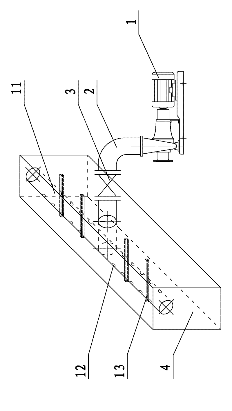
[0033] Depend on figure 1 As shown, the present invention is mainly composed of two parts, the water distribution system and the ecological treatment area. figure 2 As can be seen in the figure, the water distribution system is mainly composed of a lifting pump 1, a water inlet pipe 2, a control gate valve 3, a water distribution pipe 11, a water distribution hole 12 and a support beam 13. image 3 It can be seen from the figure that the ecological treatment area mainly includes the A-level ecological treatment area 4, the B-level ecological treatment area 5 and the bottom water corridor 15.

[0034] The invention is a bank type, which is arranged on the river bank of the discharge outlet of the urban sewage treatment plant and does not occupy the area of ​​the plant. Determine the size of the system and the size of the pipeline according to the discharge volume of the tail water and the appropriate hydraulic retention time.

[0035] Lifting water pump 1 is used to lift th...

Embodiment 2

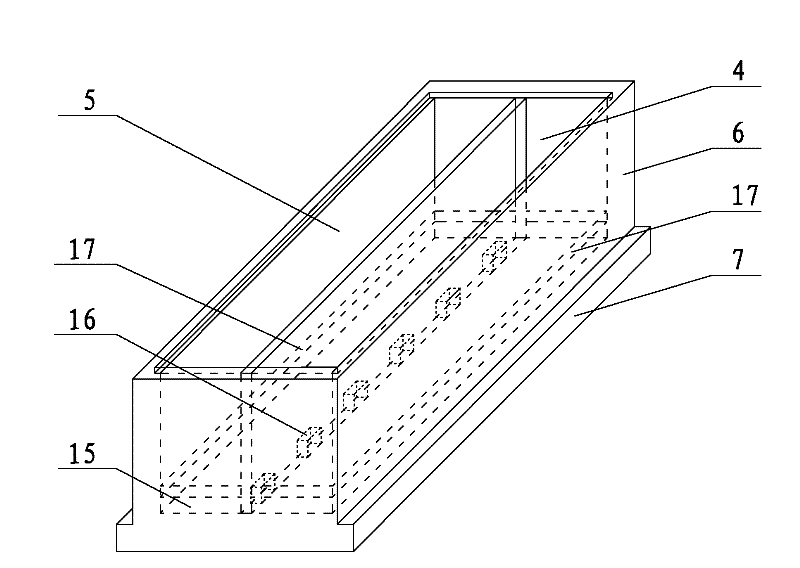
[0041]The riverside tail water treatment system device is installed on the bank of the river section of the tail water discharge outlet of the urban sewage plant, including the treatment tank. The water surface of the treatment tank is a permeable outer wall 10, and a partition wall 14 is arranged inside the treatment tank, and the partition wall separates the treatment tank. It is an A-level ecological treatment area 4 and a B-level ecological treatment area 5. The partition wall is located at the bottom of the treatment pool and is provided with a water hole 16. The A-level ecological treatment area 4 and the B-level ecological treatment area 5 are connected through the water hole 16. A water-permeable support partition 17 is provided on the horizontal surface of the water hole 16 in the pool, and the space between the support partition 17 and the base 7 of the treatment pool forms a water passage 15, and a sewage treatment area 4 is provided in the A-level ecological treatmen...


PUM

PropertyMeasurementUnit
Water permeability coefficientaaaaaaaaaa

Abstract

The invention relates to a riverbank-type tail water treatment system, which is located at riverbank of the tail water discharge port of an urban sewage treatment plant and comprises a treatment pond, wherein the surface facing to water, of the treatment pond is a water-permeable outer wall; a partition is arranged in the treatment pond; the partition divides the treatment pond into an A-level ecological treatment region and a B-level ecological treatment region; water passing holes are formed on the partition and at the bottom of the treatment pond; a water-permeable supporting clapboard is arranged on the horizontal surfaces of the water passing holes inside the treatment pond; a water passing channel is formed in the space between the supporting clapboard and the base of the treatment pond; and a sewage inflow pipe and a sewage distribution device are arranged in the A-level ecological treatment region. The tail water treatment system has the advantages of simple structure, long service life, low maintenance cost and no occupied factory area; in the tail water treatment system, a large-resistance water distribution system is applied in the deep purification of the tail water soas to realize uniform water distribution, the tail water is further intercepted and purified before entering the river, the emission mode of the tail water is changed, the ecological influence on a river channel caused by concentrated tail water discharge is reduced; and the tail water treatment system can be combined with river regulation engineering to be used as the bank hydrophilic corridor and landscape.

Description

[0001] technical field [0002] The invention relates to the technical field of sewage treatment, in particular to a river bank tail water treatment system device. [0003] Background technique [0004] With the continuous improvement of urban water pollution control level and water environment protection requirements, the water treatment rate and discharge requirements of urban sewage treatment plants will also continue to increase. The tail water of urban sewage treatment plants will be an important source of water environment pollution in the future. Regardless of whether the sewage discharge standard of urban sewage plants adopts the first-class A standard or meets the requirements for landscape water use, there is still a big gap between the water quality of the urban sewage plant and the water quality requirements of Class IV of the surface water environment quality. At the same time, due to the insufficient surface water runoff and the decline in self-purification c...

Claims


Application Information

Patent Timeline
IPC IPC(8): C02F9/14
Inventor 朱亮吴薇李勇倪利晓汤颖钱静陈阳赵鑫磊
Owner HOHAI UNIV
Why Eureka
Try Eureka