Silicon rod self-centering synchronous clamping device

A synchronous clamping and self-centering technology, applied in the direction of working accessories, stone processing equipment, manufacturing tools, etc., can solve the problems of complex process, low cutting efficiency, low debugging efficiency, etc.

Inactive Publication Date: 2011-12-07
CHANGZHOU TIANZE PV EQUIP MFG
View PDF0 Cites 15 Cited by
  • Summary
  • Abstract
  • Description
  • Claims
  • Application Information

AI Technical Summary

Problems solved by technology

These two silicon rod cutting processes have shortcomings in the actual processing process. The first process method needs to glue the single crystal silicon rods, and heat the sol after the processing is completed. The process is very complicated. The cutting machine It needs to be equipped with auxiliary devices such as indexing mechanism, and the cutting efficiency is very low. At the same time, it is impossible to eliminate the difference between the end face of the silicon rod and the silicon rod after the previous cutting process due to the poor outer roundness of the single crystal silicon rod and the rough and irregular surface. The defect that the central axis is not vertical, because in the squaring process, the positioning short axis is glued with the end face of the single crystal silicon rod, it is easy to cause the silicon rod to be scrapped during the squaring process. The disadvantages of this squaring process are: The silicon ingot needs to be clamped twice to complete the squaring process, and the single crystal silicon ingot must be calibrated manually for each clamping. The operation is cumbersome, the debugging efficiency is very low, and the squaring is easy to be scrapped.

Method used


Image

  • Silicon rod self-centering synchronous clamping device
  • Silicon rod self-centering synchronous clamping device
  • Silicon rod self-centering synchronous clamping device

Examples


specific Embodiment approach

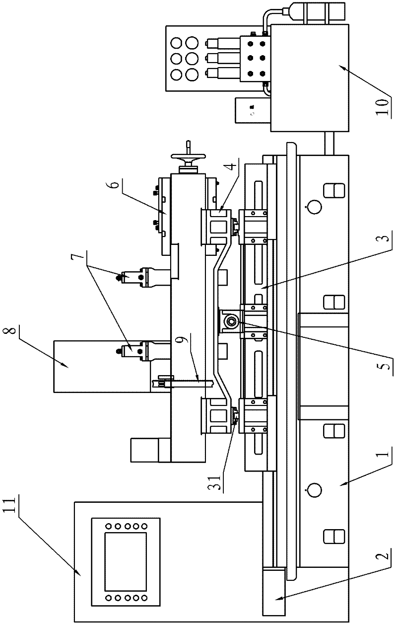
[0015] figure 1 It is a schematic structural view of the silicon rod cutting machine of the present invention, which includes a feed slide pedestal 1, a feed motor 2, a feed slide 3, a longitudinal feed slide 4, a longitudinal feed motor 5, a pressing device 6, Self-centering synchronous clamping device 7, band saw side stand 8, saw blade 9, hydraulic station 10 and electric control box 11, feed slide 3 is installed on feed slide base 1, feed slide 3 and feed A screw nut linear motion mechanism driven by the feed motor 2 is provided between the feed slide pedestal 1; a longitudinal slide rail 31 is provided on the feed slide 3, and the longitudinal feeding slide 4 and the feed slide 3 are vertically connected. The slide rail 31 is slidably matched, and a screw nut linear motion mechanism driven by the longitudinal feeding motor 5 is provided between the longitudinal feeding slide table 4 and the feed slide table 3; the top pressing device 6 is as figure 2 As shown, it includ...


PUM


Abstract

A self-centering synchronous clamping device for silicon rods, wherein the self-centering positioning clamping unit group includes a moving guide seat, a clamping oil cylinder, an upper clamping seat slide plate, a lower clamping seat slider, gears, and a lower V-shaped block And the upper V-shaped block, the upper clamping seat slide plate and the lower clamping seat slide block are set on the vertical guide rail of the moving guide seat, the gear is installed on the moving guide seat, and the gear is simultaneously connected with the rack on the upper clamping seat slide plate Side A meshes with rack side B on the slider of the lower clamping seat, the lower V-shaped block is installed on the slider of the lower clamping seat, the upper V-shaped block is installed on the sliding plate of the upper clamping seat, and the lower V-shaped block and the upper The symmetry line of the V-shaped supporting surface of the V-shaped block is on the same straight line, and the two are symmetrically distributed; the upper clamping seat slide plate and the lower clamping seat slide block are driven by the clamping oil cylinder. Its function is to accurately locate and pre-clamp the silicon rod segment, and provide accurate positioning for the final clamping of the pressing device.

Description

Technical field: [0001] The invention relates to a silicon rod cutting machine, in particular to a silicon rod positioning and clamping device of the silicon rod cutting machine. Background technique: [0002] In the production process of solar cell modules, the processing of silicon rods produced in the crystal pulling workshop into silicon wafers must go through the processes of cutting off multiple ends, cutting into sections, cutting into squares and slicing in sequence. After the silicon rods are cut into silicon rod segments, they must be The square cutting machine cuts the silicon rod section into a square with rounded corners, commonly known as square cutting. At present, there are mainly two types of silicon rod cutting machines according to the cutting tools. The first is a band saw blade cutting machine, and the other is a saw disc cutting machine. Before cutting the band saw blade cutting machine, one end of the cut monocrystalline silicon rod and the positionin...

Claims


Application Information

Patent Timeline
Patent Type & Authority Applications(China)
IPC IPC(8): B28D7/04
Inventor 于金文陈胜何进崔正
Owner CHANGZHOU TIANZE PV EQUIP MFG
Why Eureka
Try Eureka