Method for recovery and utilization of waste heat from low temperature flue gas

A technology of waste heat recovery and low-temperature flue gas, applied in heating methods, applications, preheating, etc., can solve problems such as waste and achieve the effect of heat energy saving

Inactive Publication Date: 2011-12-07
LUOYANG BLUE SEA INDAL
View PDF5 Cites 41 Cited by
  • Summary
  • Abstract
  • Description
  • Claims
  • Application Information

AI Technical Summary

Problems solved by technology

This part of the heat is currently emitt

Method used


Image

  • Method for recovery and utilization of waste heat from low temperature flue gas
  • Method for recovery and utilization of waste heat from low temperature flue gas
  • Method for recovery and utilization of waste heat from low temperature flue gas

Examples


Embodiment 1

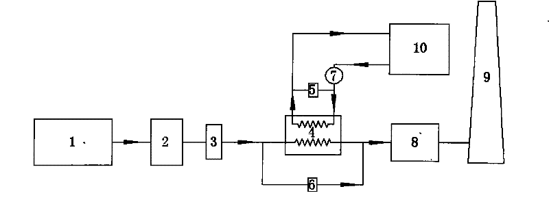
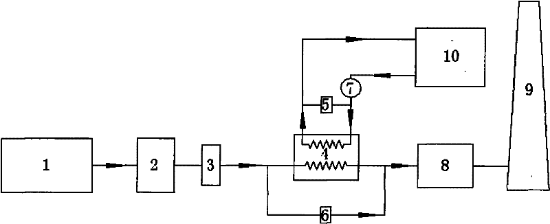
[0012] like figure 1 As shown: this embodiment is a device for heating circulating water, mainly composed of a boiler or kiln 1, a dust collector 2, an induced draft fan or a booster fan 3, an air-water heat exchanger 4, a waterway bypass regulating valve 5, The flue bypass regulating valve 6, the circulation pump 7, the desulfurization absorption tower 8, the chimney 9, and the heat user 10 constitute. Each part is connected by pipes, accessories, valves, etc. The air-water heat exchanger 4 (patent applied for separately) is connected in series or in parallel in the flue between the induced draft fan or booster fan 3 and the desulfurization absorption tower 8, the hot side inlet end of the air-water heat exchanger 4 is connected to the induced draft fan Or the booster fan 3 is connected, the outlet end of the hot side is connected with the desulfurization absorption tower 8 or the chimney 9, the inlet end of the cold side is connected with the return water end of the hot use...

Embodiment 2

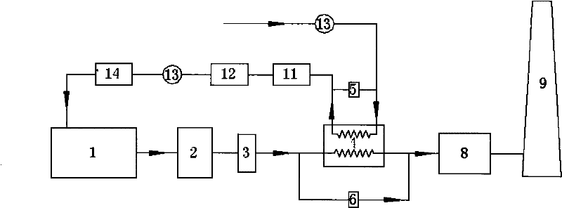
[0014] like figure 2 As shown: this embodiment is the device for heating boiler feed water according to the present invention, which is mainly regulated by boiler or kiln 1, dust collector 2, induced draft fan or booster fan 3, air-water heat exchanger 4, and water bypass Valve 5, flue bypass regulating valve 6, circulation pump 7, desulfurization absorption tower 8, chimney 9, low pressure heater 11, deaerator 12, feed water pump 13 and high pressure heater 14. Each part is connected by pipes, accessories, valves, etc. The air-water heat exchanger 4 (patent applied for separately) is connected in series or in parallel in the flue of the induced draft fan or booster fan 3 and the desulfurization absorption tower 8, the hot side inlet end of the air-water heat exchanger 4 is connected with the induced draft fan or The compressor 3 is connected, the hot side outlet is connected to the desulfurization absorption tower 8 or the chimney 9, the cold side inlet of the air-water hea...


PUM


Abstract

The invention discloses a method for recovering and utilizing waste heat from low-temperature flue gas. An air-water heat exchanger (4) is connected in series or in parallel in the flue at the rear of the induced draft fan or booster fan (3) of the existing boiler or kiln (1). The inlet port of the hot side of the air-water heat exchanger is connected with the induced draft fan or booster fan (3), the outlet port of the hot side is connected with the desulfurization absorption tower (8) or the chimney (9), and the inlet port of the cold side is circulated with the heat user The outlet pipe or condensate pipe of the water or boiler softened water system is connected, the cold side outlet is connected with the hot user circulating water supply or the boiler feed water pump, and a waterway is connected between the hot side outlet pipe and the cold side inlet pipe of the air-water heat exchanger A bypass pipe, and a waterway bypass regulating valve (5) is arranged on the pipe; a flue gas bypass pipe between the induced draft fan or booster fan and the desulfurization absorption tower (8), and a flue gas bypass pipe A flue bypass regulating valve (6) is arranged on it. By connecting a gas-water heat exchanger in series or in parallel in the flue behind the induced draft fan of the boiler or kiln, the purpose of saving heat energy can be achieved.

Description

technical field [0001] The invention belongs to the technical field of waste heat recovery and utilization, and mainly relates to a method for recovery and utilization of low-temperature flue gas waste heat. Background technique [0002] In thermal power plants and industrial production, the amount of smoke exhausted by boilers is very large. The current production process is that the flue gas at about 150°C is desulfurized by the desulfurization process and then discharged into the atmosphere through the chimney. Due to the existence of low-temperature condensation corrosion and the resulting sticky fouling problem, existing heat exchangers must avoid the exhaust gas temperature at the outlet of the heat exchanger being too low during design, so as to ensure the service life and safety of the heat exchanger. Therefore, for the low exhaust gas temperature of about 150°C, the existing heat exchangers cannot fundamentally solve the problem of low-temperature condensation corr...

Claims


Application Information

Patent Timeline
IPC IPC(8): F22D1/02F24D3/02F27D17/00
CPCY02P10/25
Inventor 曹辉王龙江张嘉田玉善刘海国杨艳辉冯俊乐聂玉涛张继光
Owner LUOYANG BLUE SEA INDAL
Why Eureka
Try Eureka