Co2 compression liquefaction system combined with waste heat driven refrigeration

A refrigeration system and combined technology, applied in the field of CO2 compression liquefaction system, can solve the problems of reducing compression power, high compression power consumption, low energy consumption, etc., and achieve the effects of reducing power consumption, reducing power consumption, and increasing waste heat utilization.

Inactive Publication Date: 2011-12-07
NORTH CHINA ELECTRIC POWER UNIV (BAODING)
View PDF6 Cites 15 Cited by
  • Summary
  • Abstract
  • Description
  • Claims
  • Application Information

AI Technical Summary

Problems solved by technology

[0003] The present invention solves the problem of traditional compressed liquefied CO 2 Due to the high power consumption of system compression, a compressed liquefied CO combined with waste heat-driven refrigeration is proposed. 2 The system can effectively reduce the compressed liquefied CO 2 The compression work of the process and the total energy consumption can also be kept in a low range

Method used


Image

  • Co2 compression liquefaction system combined with waste heat driven refrigeration
  • Co2 compression liquefaction system combined with waste heat driven refrigeration
  • Co2 compression liquefaction system combined with waste heat driven refrigeration

Examples


Embodiment Construction

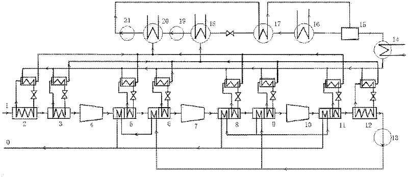
[0016] The present invention provides a CO combined with waste heat driven refrigeration 2 Compression liquefaction system, the present invention will be further described below through the description of the drawings and specific embodiments.

[0017] The structural diagram of the present invention is as figure 1 Shown: CO 2 gas from CO 2 The gas inlet 1 enters, and flows through the first-stage evaporator 2, the second-stage evaporator 3, the first-stage compressor 4, the third-stage evaporator 5, the fourth-stage evaporator 6, the second-stage compressor 7, The fifth-stage evaporator 8, the sixth-stage evaporator 9, the third-stage compressor 10, the seventh-stage evaporator 11, the eighth-stage evaporator 12, and the liquid oxygen pump 13, and then sequentially pass through the fourth-stage evaporator 6, the heat exchanger before the third-stage evaporator 5, and the heat exchanger installed before the sixth-stage evaporator 9, the fifth-stage evaporator 8, and the seve...


PUM


Abstract

The invention belongs to the technical field of CO2 post treatment, and in particular relates to a CO2 compression and liquefaction system combined with waste heat driven refrigeration. Based on the CO2 compression and liquefaction system consisting of a multistage compressor, a cooler and a circulating water system, a CO2 gas pre-cooling system, an ammonia absorption type refrigerating system, astaged cooling system, a waste heat steam extraction system, a liquid oxygen pump supercharging system and a liquid CO2 cold reclaiming system are additionally provided; and through the measures of combining the rich waste heat environment of a power plant, making cold by using a waste heat driven refrigerating machine, reducing the liquefaction pressure of CO2 with low temperature and raising the pressure by using the pump after the CO2 is liquefied and the like, the total CO2 compression power consumption is reduced, the electrical energy is saved, and the heat efficiency of the whole plantis improved. The system is suitable for multiple occasions supplied with waste heat and required for compressing and liquefying CO2, and particularly can effectively utilize the waste heat of the power plant and reduce the energy consumption level of CO2 compression and liquefaction in the thermal power plant required for reclaiming the CO2.

Description

technical field [0001] The invention belongs to CO 2 Post-processing technical field, especially a kind of CO combined with waste heat-driven refrigeration 2 Compression liquefaction system. Background technique [0002] Currently, due to the powertrain CO 2 The greenhouse effect caused by emissions is becoming more and more serious, therefore, CO 2 The capture, storage and utilization of sequestration has become a hot research topic both at home and abroad. CO capture from powertrain 2 Before being stored, it needs to be compressed to a pressure of 80 bar or higher to become liquid, which is beneficial for long-distance transmission. However, this process consumes a lot of work. Traditional methods usually use multi-stage serial compression step by step, and the CO 2 Compress gas above critical pressure to liquefy CO 2 , high pressure and liquid CO can be obtained simultaneously 2 , which is the main technical route currently popular. This direct compression metho...

Claims


Application Information

Patent Timeline
Patent Type & Authority Applications(China)
IPC IPC(8): F25J1/02
CPCF25J3/0266F25J3/067F25J2230/80F25J2235/80F25J2230/02F25J2230/04F25J2260/02F25J2270/906
Inventor 段立强陈新明杨勇平
Owner NORTH CHINA ELECTRIC POWER UNIV (BAODING)
Why Eureka
Try Eureka