
A grinding soybean milk machine and its automatic cleaning method

An automatic cleaning and soymilk maker technology, applied in cleaning methods and utensils, cleaning methods using liquids, chemical instruments and methods, etc. water flow and other issues, to save water resources and eliminate cumbersome steps

Inactive Publication Date: 2011-12-14
ZHEJIANG SHAOXING SUPOR DOMESTIC ELECTRICAL APPLIANCE CO LTD
View PDF6 Cites 27 Cited by
  • Summary
  • Abstract
  • Description
  • Claims
  • Application Information

AI Technical Summary

Problems solved by technology

[0005] The device is ground from top to bottom, without the function of swirling suction and backflow, so when cleaning, it cannot form a tumbling circulating water flow, let alone produce a clustered jet-like water flow. In this way, some adhered residues will be It is not easy to be cleaned off, forming dead corners for cleaning and the growth of bacteria
This will bring about problems in cleanliness, food hygiene and safety, and affect the health of drinkers.

Method used


Image

  • A grinding soybean milk machine and its automatic cleaning method
  • A grinding soybean milk machine and its automatic cleaning method
  • A grinding soybean milk machine and its automatic cleaning method

Examples


Embodiment 1

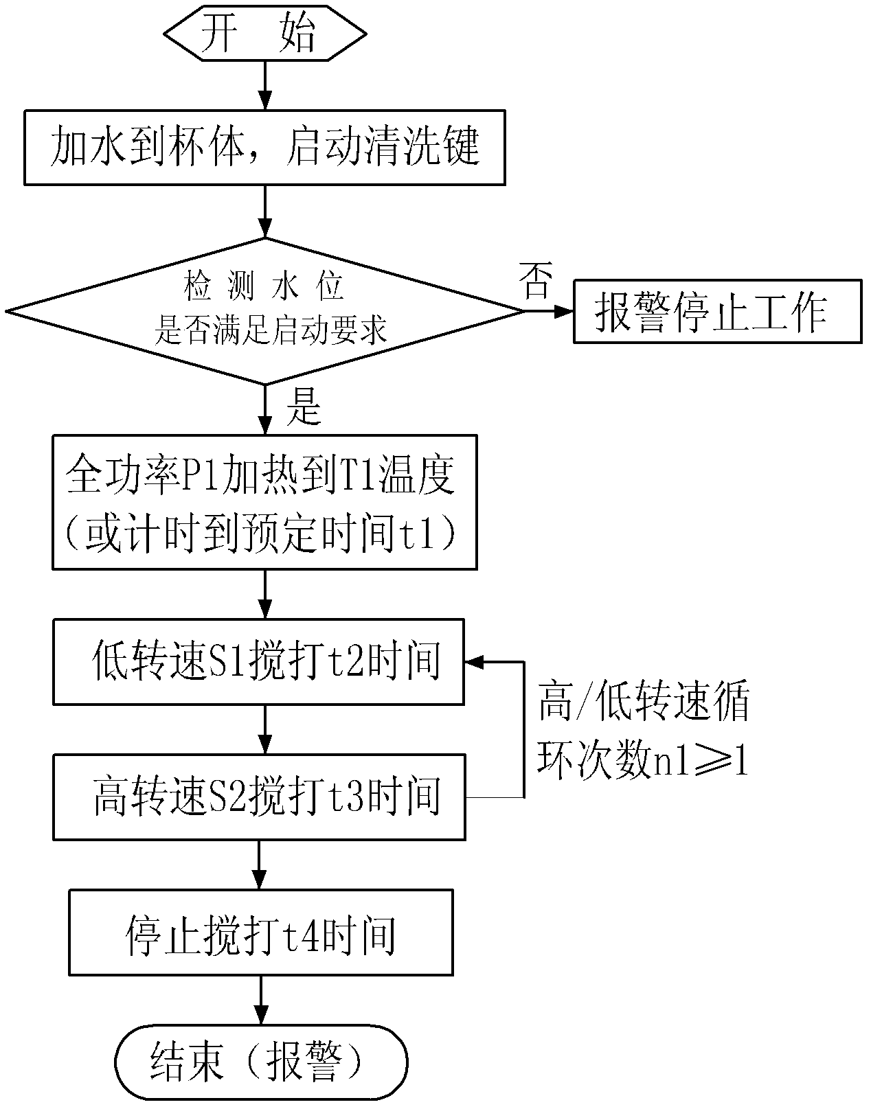
[0041] See attached figure 1 , attached Figure 6-8 , a grinding soymilk machine, a processor 81, a detection unit 83, a grinding unit 4, a main control circuit 8 of a heating unit, a machine head 1 accommodating the main control circuit 8, and a slurry container 2 connected to the machine head 1, containing The slurry container 2 is provided with a movable grinding head 41 connected to the motor shaft in the machine head and a static grinding head 42 matched with the moving grinding head 41. The space forms a concentrated water flow for cleaning.

[0042] The moving grinding head 41 and the static grinding head 42 are all provided with grinding teeth on the mating surfaces, and when the grinding teeth are mated, there is generally a matching gap from large to small from bottom to top. The moving grinding head 41 can produce a certain rotational suction force when moving. When the motor 3 rotates at a high speed, the rotary suction force formed by the movable grinding head 4...

Embodiment 2

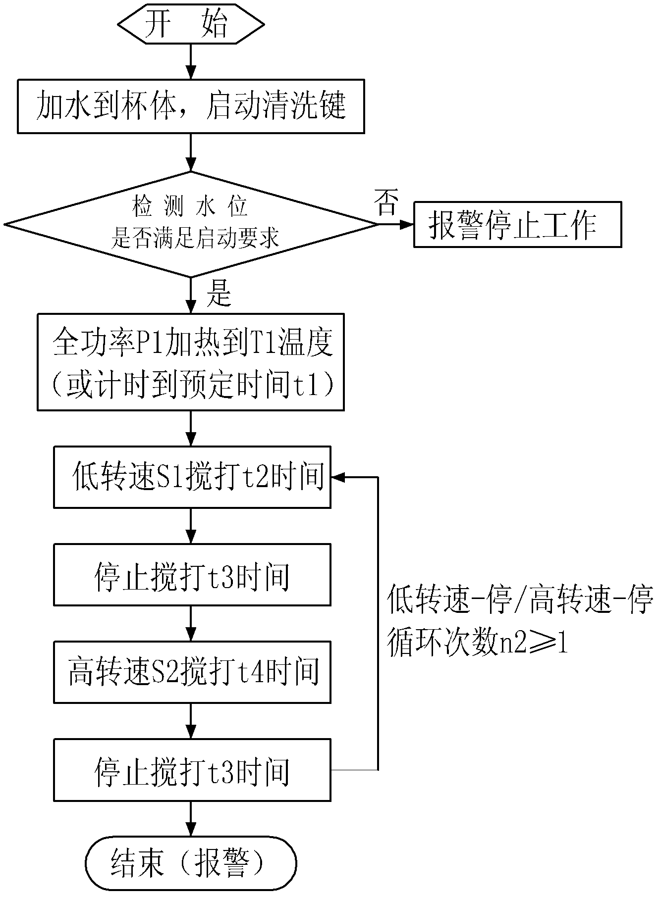
[0055] See attached figure 2 , attached Figure 6-8 , in order to protect the motor 3, after the low speed S1 whipping time t2 is completed, it is necessary to stop the whipping time t3, and then switch to the high speed S2 whipping time t4, the process in the cleaning stage is as follows: low speed S1 whipping Beating time t2→stop whipping time t3→high speed S2 whipping time t3→stop whipping time t3. It is a cycle of low rotation speed S1 and high rotation speed S2, and the number of cycles n2 is specifically 1 time. After that, the whipping will stop, an alarm will be given to remind the user, and the entire cleaning process will be completed. Other steps are the same as in Embodiment 1.

Embodiment 3

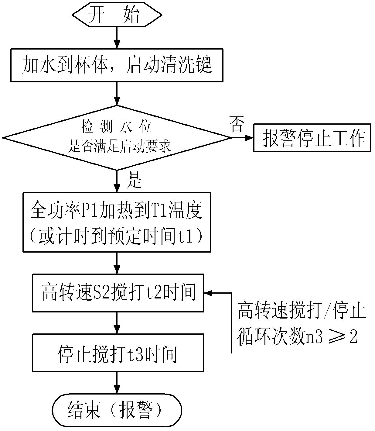
[0057] See attached image 3 , attached Figure 6-8 , in the cleaning stage, the motor speed is a single speed, that is, the motor 3 drives the grinding unit 4 at a single constant speed, combined with different grinding structures in the grinding soybean milk machine to whip and clean at a high speed, for example, set on the grinding unit 4 A diversion device, high-speed water flow through the diversion device to perform high-intensity scouring and cleaning of the grinding unit 4 and the slurry container 2, and the high-speed S2 whipping time t2 stops whipping, and the number of cycles n3 is specifically 2 times, Until the whipping is stopped, the cleaning is completed and an alarm is given to the user to complete the entire cleaning process. Other steps are the same as in Embodiment 1.


PUM


Abstract

The invention belongs to the field of small kitchen appliances, and in particular relates to a soymilk machine, especially a grinding type easy-to-clean soymilk machine. The motor and a main control circuit in the machine head are provided with a grinding unit consisting of a dynamic grinding head and a static grinding head at the lower part of the machine head. And the automatic cleaning is realized by the following stages: a) feeding stage, b) detecting water level stage, c) heating stage H1, d) completing the whole cleaning process after the cleaning stage. The grinding soybean milk machine and its automatic cleaning method of the present invention are automatic cleaning of the machine, eliminating the cumbersome steps of manual scrubbing. During cleaning, the cooperation of the grinding head produces a high-intensity clustered water flow, and realizes automatic tumbling according to different changes in the motor. Water flow, multi-angle cleaning, no cleaning dead angle.

Description

technical field [0001] The invention belongs to the field of small kitchen appliances, in particular to a soybean milk maker, in particular to a grinding soybean milk maker and an automatic cleaning method thereof. Background technique [0002] At present, as a common household appliance, soymilk makers have gradually entered the households of ordinary people. The cleaning method of soymilk makers on the existing market is generally to connect a crushing tool to the motor in the machine head, and cooperate with the crushing tool to achieve crushing and cleaning. The structure mainly has the following two types: the first one is to set a turbulence net at the lower part of the machine head, and the crushing cutter is set in the turbulence net, and the crushing knife realizes the purpose of cleaning by whipping in the small space of the turbulence net The second is to set the disturbing flow ribs on the inner wall of the cleaning container, and when the crushing cutter rotates...

Claims


Application Information

Patent Timeline
IPC IPC(8): A47J31/44A47J31/60A23C11/10B08B3/02
Inventor 蔡才德张锦洲陈世雄湛海耀
Owner ZHEJIANG SHAOXING SUPOR DOMESTIC ELECTRICAL APPLIANCE CO LTD
Learn More