Shaking arc narrow gap melting electrode gas shielded vertical welding method

A technology of molten electrode gas and welding method, which is applied in the direction of arc welding equipment, welding equipment, manufacturing tools, etc., can solve the problems of difficult narrow gap multi-layer vertical welding and low efficiency, so as to improve welding efficiency and reduce production cost , The effect of small groove gap

Active Publication Date: 2011-12-14
JIANGSU UNIV OF SCI & TECH
View PDF16 Cites 31 Cited by
  • Summary
  • Abstract
  • Description
  • Claims
  • Application Information

AI Technical Summary

Problems solved by technology

[0006] Aiming at the shortcomings of the existing shaking arc narrow-gap melting electrode gas shielded welding method that it is difficult to realize narrow-gap multi-layer vertical welding and the existing thick plate automatic vertical welding method is low in efficiency, the present invention proposes a practical and low implementation cost , High welding efficiency shaking arc narrow gap melting electrode gas shielded vertical automatic welding method

Method used


Image

  • Shaking arc narrow gap melting electrode gas shielded vertical welding method
  • Shaking arc narrow gap melting electrode gas shielded vertical welding method
  • Shaking arc narrow gap melting electrode gas shielded vertical welding method

Examples


Embodiment 1

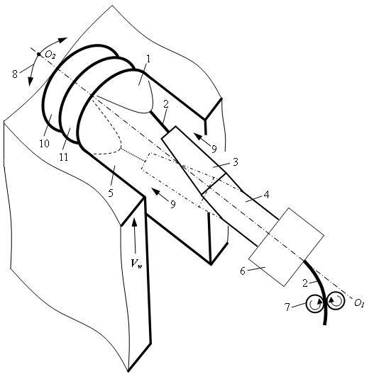
[0030] The vertical groove 5 to be welded is an I-type welded groove with a gap of 12 mm. During welding, the vertical groove 5 to be welded is in a vertical position. Other welding parameters are: the bending angle of the slightly curved conductive rod 4 is 3°, the arc shaking frequency is 2.0 Hz, the arc shaking angle is 60°, the residence time of the arc 1 on the two side walls of the vertical groove 5 to be welded is respectively The average welding current is 200A, the average arc voltage is 26V, and the welding speed is 15cm / min. The obtained macroscopic photograph of the cross-section of the weld is shown in Figure 3(a). The middle part of the formed weld surface is slightly convex, and the two side walls vertically to the groove 5 to be welded are evenly and symmetrically penetrated.

Embodiment 2

[0032] The vertical groove 5 to be welded is an I-type welded groove with a gap of 14 mm, and the vertical groove 5 to be welded is in a vertical position during welding. Other welding parameters are: the bending angle of the slightly curved conductive rod 4 is 8°, the arc shaking frequency is 0.8 Hz, the arc shaking angle is 84°, the residence time of the arc 1 on the two side walls of the vertical groove 5 to be welded is respectively The average welding current is 155A, the average arc voltage is 22V, and the welding speed is 9.1cm / min. The obtained macroscopic photograph of the cross-section of the weld is shown in Figure 3(b). The surface of the formed weld is flat, and the penetration of the two side walls of the vertical groove 5 to be welded is uniform and symmetrical.

Embodiment 3

[0034] The vertical groove 5 to be welded is an I-type welded groove with a gap of 16 mm, and the vertical groove 5 to be welded is in a vertical position during welding. Other welding parameters are: the bending angle of the slightly curved conductive rod 4 is 15°, the shaking frequency of the arc is 0.4 Hz, the shaking angle is 180°, and the residence time of the arc 1 on the two side walls of the vertical groove 5 to be welded is respectively 600ms, the average welding current is 140A, the average arc voltage is 18V, and the welding speed is 7cm / min. The penetration of both side walls of the welding groove 5 is uniform and symmetrical.

[0035] It can be seen from the above three embodiments and Fig. 3 that the shaking arc narrow-gap gas-shielded vertical weld is well formed, which shows that this method has strong practicability. In addition, for this free-formed well-formed weld, at the bottom of each layer of weld along the plate thickness direction, a penetration with ...


PUM

PropertyMeasurementUnit
angleaaaaaaaaaa
angleaaaaaaaaaa
angleaaaaaaaaaa

Abstract

The invention discloses a rocking-arc narrow-gap vertical gas metal arc welding method comprising the following steps of: assembling metal-piece thick plates into an I-shaped vertical groove to be welded having a gap within a range of 12-15 mm; according to the gap of the groove to be welded and the difference of weld joint passes, firstly selecting a gas protection way, setting an arc rocking frequency, an arc rocking amplitude, arc side wall retention time, an average arc current of pulse welding, an average arc voltage, a welding speed and the dry extension of a welding wire, and selectinga slightly bent conductive rod with an appropriate bending angle; moving a welding torch integrally upwards or downwards in the vertical direction at the welding speed, thereby realizing vertical andautomatic rocking-arc narrow-gap gas metal arc welding in such a manner of single-pass multi-layer welding per layer in a state where a weld joint is freely formed. The method of the invention does not need to form a large welding groove and does not require a forced forming device; besides, the welding device is simple, the welding efficiency is high, the weld joint is formed beautifully, and the performance of the welded joint is good.

Description

technical field [0001] The invention relates to the field of welding technology, in particular to a gas-shielded vertical welding method with a narrow gap of an oscillating arc. Background technique [0002] Vertical welding is suitable for on-site welding of large or extra-large workpieces. It refers to a process of welding vertically upward (from bottom to top) or vertically downward (from top to bottom) along the length of the weld in the vertical plane. At this time, the liquid metal and molten droplets in the molten pool are prone to dripping under the influence of their own gravity, which makes it difficult to form the weld freely and affects the quality of the joint. The traditional vertical automatic welding of melting poles mainly includes gas-electric vertical welding and electroslag welding, etc., the groove gap used in the implementation process is large, the welding heat input is high, and the forced forming mechanism is required, so the welding device is compli...

Claims


Application Information

Patent Timeline
Patent Type & Authority Applications(China)
IPC IPC(8): B23K9/16
Inventor 王加友朱杰苏荣近王彪
Owner JIANGSU UNIV OF SCI & TECH
Why Eureka
Try Eureka