Evaporation or sublimation method and crucible device for evaporation material in vacuum evaporation device

A technology for vapor deposition materials and crucibles, which is applied in the field of crucible devices for vacuum vapor deposition, can solve the problems of complicated devices, reduced quality of vapor deposition materials, and adverse effects on film formation, and achieves a simple structure and the effect of preventing deterioration.

Active Publication Date: 2011-12-14
HITACHI ZOSEN CORP
View PDF6 Cites 18 Cited by
  • Summary
  • Abstract
  • Description
  • Claims
  • Application Information

AI Technical Summary

Problems solved by technology

[0008] However, the above scheme A) requires a crucible replacement device to be installed in the vapor deposition chamber in a vacuum state, resulting in an increase in the overall size of the vapor deposition device.
[0009] B) The scheme requires a supplementary device for evaporating materials, and taking into account the supplementary control, it will lead to complex installations
[0010] C) The solution requires equipment for forming the vapor deposition material into particles and a pressurizing device for pushing the granular vapor deposition material on the heating source, which will increase the cost of the equipment
[0011] In addition, in the proposal of Patent Document 1, if the evaporated and sublimated vapor deposition material comes into contact with a heating device heated to a high temperature, thermal decomposition will occur, which will degrade the quality of the vapor deposition material and have a bad influence on film formation.
[0012] In addition, in the prior art that heats the vapor deposition material with a laser beam to vaporize and sublimate, the vapor deposition material tends to adhere and accumulate on the inner surface of the crucible.

Method used


Image

  • Evaporation or sublimation method and crucible device for evaporation material in vacuum evaporation device
  • Evaporation or sublimation method and crucible device for evaporation material in vacuum evaporation device
  • Evaporation or sublimation method and crucible device for evaporation material in vacuum evaporation device

Examples


Embodiment 1

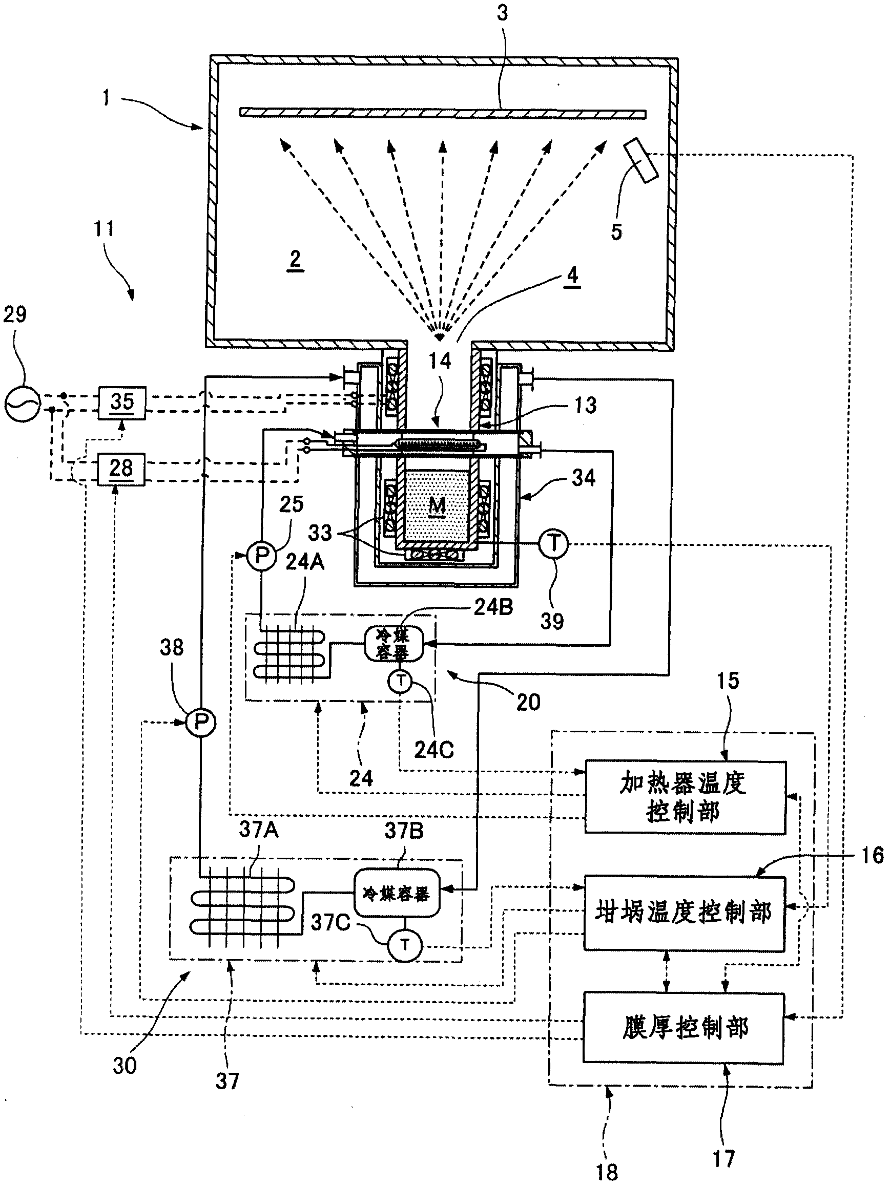
[0074] Such as figure 1 As shown, the vacuum evaporation device is an upper deposition structure. In the upper deposition type vacuum evaporation device, in the upper part of the inner side of the vacuum evaporation chamber 2 formed by the vacuum container 1, the substrate 3 as the member to be evaporated is arranged by means of a holding member (not shown). A material discharge port 4 is provided at the bottom. Furthermore, a material evaporating device 11 is provided outside the vacuum container 1 for heating, evaporating and sublimating the evaporation material M, and the material evaporating device 11 communicates with the material discharge port 4 . An opening with an opening and closing door for allowing the substrate 3 to enter and exit is also formed in the vacuum container 1 , which is not shown in the figure.

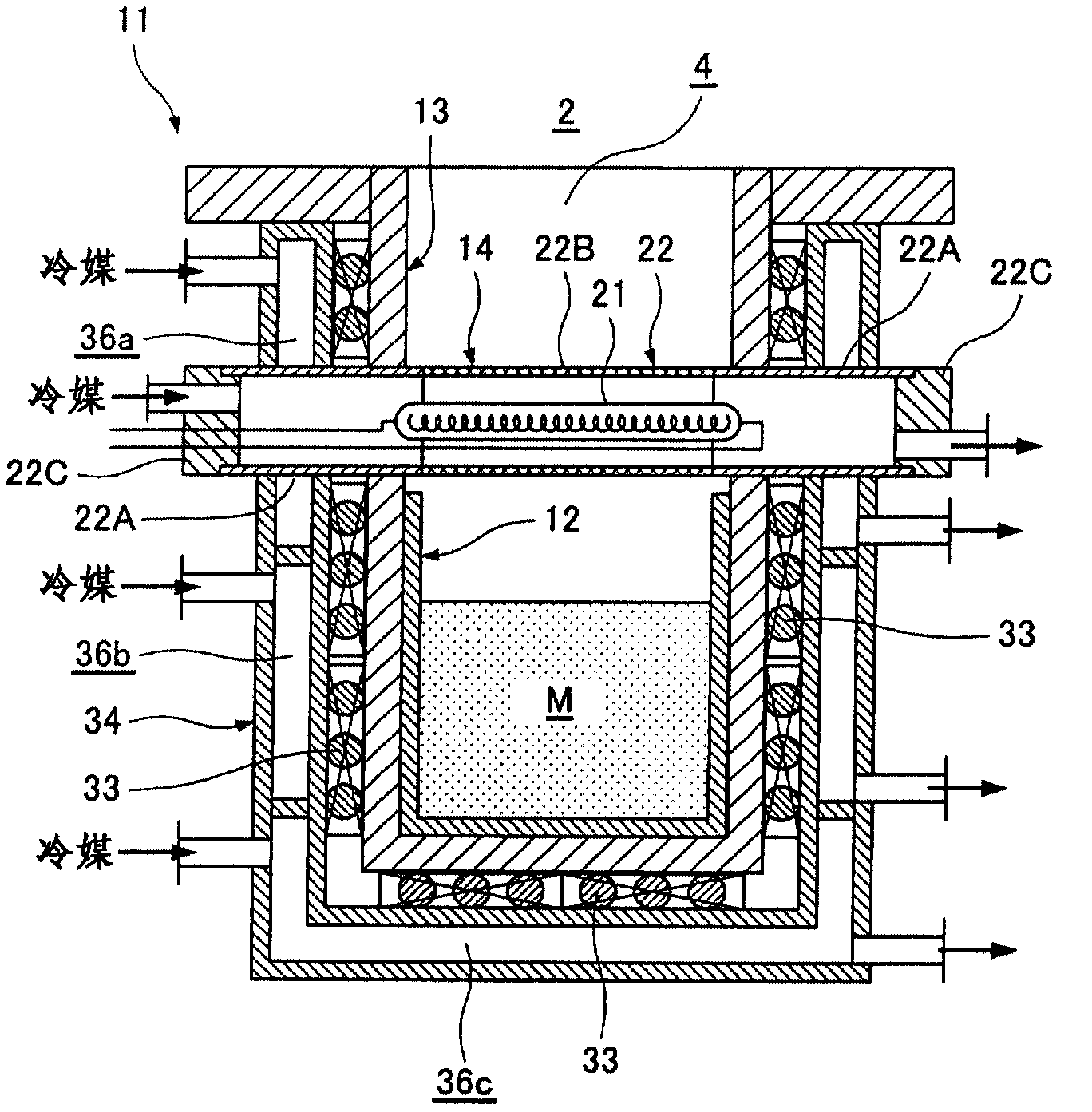
[0075] Such as figure 2 As shown, the crucible arranged on the material evaporation device 11 includes: a crucible main body 12, which is used to accommod...


PUM


Abstract

The invention provides an evaporation or sublimation method of evaporation material in a vacuum evaporation unit, and a crucible unit for vacuum evaporation. The units can work continuously for a long term and prevent the degradation of the evaporation material. In a crucible base (13), a radioactive heat source (21) radiating heat waves mainly including infrared ray is disposed in a heat wave transmission tube (22). The heat wave transmission tube (22) is made of material through which the infrared ray can transmit. The heat waves from the radioactive heat source (21) emit on the surface of the evaporation material M in a crucible body (12) and heat the evaporation material to make the surface of the evaporation material M for evaporation or sublimation. Even if the evaporated or sublimated evaporation material M is adhered on the surface of the heat wave transmission tube (22) or the inner surfaces of the crucible body (12) and the crucible base (13), the heat waves can be used to make the evaporated or sublimated evaporation material M for evaporation or sublimation again.

Description

technical field [0001] The present invention relates to a method for evaporating or sublimating an evaporation material in a vacuum evaporation device and a crucible device for vacuum evaporation, wherein an evaporation material including an organic evaporation material is heated for a long period of time without deterioration, and evaporated or sublimated , for vacuum evaporation. Background technique [0002] In the mass production process of substrates and the like to be subjected to vacuum evaporation, continuous operation is performed, and the evaporation material is heated for a long time, for example, about one week, to be evaporated and sublimated, and vacuum evaporation is performed on the substrates and the like. Such long-term continuous operation requires preventing the vapor deposition material from deteriorating due to prolonged heating. [0003] In the prior art, the following scheme is adopted for long-term continuous operation: [0004] A) A plurality of c...

Claims


Application Information

Patent Timeline
Patent Type & Authority Applications(China)
IPC IPC(8): C23C14/28
CPCC23C14/12C23C14/243C23C14/26C23C14/28C23C14/544H10K71/00
Inventor 上川健司
Owner HITACHI ZOSEN CORP
Why Eureka
Try Eureka