
Ground temperature-adjusting snow-melting device and temperature-adjusting ground structure using natural geothermal heat

A ground and geothermal technology, applied in the field of geothermal utilization systems, can solve the problems of increased emissions, increased energy consumption, pollution, etc., to achieve the effects of preventing freezing or melting frost and snow, easy maintenance and simple system structure

Active Publication Date: 2015-08-12
尹学军 +1
View PDF8 Cites 1 Cited by
  • Summary
  • Abstract
  • Description
  • Claims
  • Application Information

AI Technical Summary

Problems solved by technology

However, since this technical solution uses antifreeze as a heat exchange medium, once the antifreeze denatures and freezes and solidifies, the pipeline will be blocked, making the system unable to achieve normal heat circulation. Therefore, the antifreeze must be replaced regularly, and the cost is relatively high. high
Moreover, this technical solution also uses heat exchange devices to perform a heat exchange in the middle, which inevitably produces heat loss and reduces the utilization rate of geothermal energy.
In addition, installing a circulating pump in the pipeline increases energy consumption on the one hand and brings new pollution on the other hand
Therefore, this technical solution has some obvious deficiencies no matter from an economic point of view or from an environmental point of view.
[0003] In addition, when the temperature of vegetable greenhouses is low in winter, it is necessary to use soil heating to burn coal to raise the ground temperature and greenhouse temperature, which wastes energy and increases emissions

Method used


Image

  • Ground temperature-adjusting snow-melting device and temperature-adjusting ground structure using natural geothermal heat
  • Ground temperature-adjusting snow-melting device and temperature-adjusting ground structure using natural geothermal heat
  • Ground temperature-adjusting snow-melting device and temperature-adjusting ground structure using natural geothermal heat

Examples


Embodiment 1

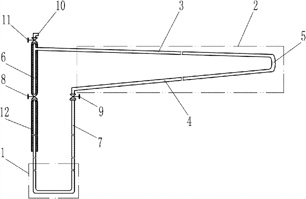
[0035] Such as figure 1 The shown ground temperature-regulating snow-melting device utilizing natural geothermal heat in the present invention includes a heat-collecting part 1, which is a U-shaped pipe, and is connected to the heat-dissipating part 2 through an output pipe 6 and a return pipe 7 to form a closed circuit. The circuit is equipped with a low-boiling-point working medium—liquid ammonia (not specifically shown in the figure) as a heat-transfer working medium, which fills most of the space inside the heat collector. The heat dissipation part 2 is composed of a heat dissipation pipe 3 and a collector pipe 4. The heat dissipation pipe 3 is higher than the collector pipe 4 and communicates with the collector pipe through the return part 5. In the heat dissipation part 2, the heat dissipation pipe 3 and the output pipe 6 The connected inlet is higher than the outlet of the header 4 connected to the return pipe 7 . In order to realize the smooth circulation of the heat ...

Embodiment 2

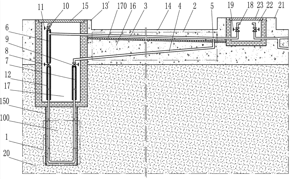
[0043] Such as Figure 4 The ground temperature-regulating snow-melting device using natural geothermal heat shown differs from Embodiment 1 in that an insulating layer 12 is also provided on the surface of the return pipe 7 in order to prevent the condensed low-boiling point working fluid from condensing in the return pipe 7 from dissipating heat to the shallow rock and soil. In addition, in order to be able to discharge the gaseous impurities mixed into the circuit with the low boiling point working fluid at any time, an exhaust port 18 and an exhaust switch valve 19 are provided at the end of the heat pipe. In this example, the inclinations of the radiator pipe and the collector pipe are 1:100 and 2:100 respectively, and the overall height of the radiator is lower.

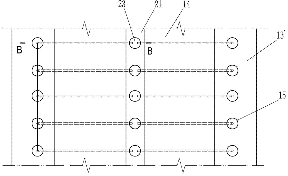
[0044] Such as Figure 5 and Figure 6The difference between the road structure shown in the above-mentioned ground temperature-regulating snow-melting device using natural geothermal heat and the first embod...

Embodiment 3

[0050] Such as Figure 7 The present invention utilizes natural ground heat to adjust the temperature and snow-melting device on the ground. The difference from Embodiment 1 is that the heat collecting part 1 is a blind pipe, and a low-boiling-point working medium 25 is arranged in the dead pipe, and the opening of the output pipe 6 is located at the top of the dead pipe. The lower end of the return pipe 7 is located at the bottom of the dead leg. In order to improve the heat dissipation efficiency, the heat dissipation part includes a plurality of heat dissipation pipes 3 arranged in parallel. In order to avoid unexpected loss of heat and unexpected heat exchange between the output pipe and the return pipe, an insulating layer 12 is provided outside the output pipe 6 and the return pipe 7 . In addition, in order to facilitate the addition of low-boiling-point working fluid into the circuit, a low-boiling-point working fluid filling port 10 and a corresponding filling switch ...


PUM


Abstract

The invention relates to a ground temperature-regulating snow-melting device utilizing natural geothermal energy and its application, belonging to a geothermal utilization system, in particular to a snow-melting device for snow and ice removal. It includes a heat collection part and a heat dissipation part. The heat collection part is connected with the heat dissipation part through the output pipe and the return pipe to form a closed circuit. The characteristic is that the circuit is equipped with a low boiling point working fluid. The cooling tube is connected with the collecting tube through the return part, the collecting tube is located under the cooling tube, the two ends of the cooling tube are respectively connected with the output tube and the return part, and the two ends of the collecting tube are respectively connected with the return part and the return part. The upper ends of the pipes are connected, and the collecting pipe is continuously inclined downward from the return part to the return pipe, and the inclination is less than 1:10. The invention utilizes the heat medium with a low boiling point in the heat collector to absorb underground heat energy, and the heat medium after absorbing heat and gasification directly transmits heat to the radiator installed under the ground or road surface, so as to prevent frost and snow from remaining on the ground or road surface Or the effect of melting frost and snow, it does not consume extra energy, is environmentally friendly and economical, and can ensure the smooth flow of roads.

Description

technical field [0001] The invention belongs to a geothermal utilization system, in particular to a ground temperature-adjusting and snow-melting device that utilizes natural underground thermal energy to remove snow and ice. Background technique [0002] In recent years, with the rapid development of China's economy, the country's investment in infrastructure construction has continued to increase, and many expressways, expressways and airports have been built and used one after another, providing great convenience for people's production, life and travel. However, in the winter and spring seasons in some northern regions, due to frequent snowfall and large temperature difference between day and night, it is easy to form snow or freeze on the road surface, seriously affecting the driving safety of vehicles or aircraft, and causing great safety hazards. In the past, for the snow on the road surface, it was mainly to use manual or snow removal vehicles to clear snow or spread...

Claims


Application Information

Patent Timeline
Patent Type & Authority Patents(China)
IPC IPC(8): E01C11/26F24J3/08
CPCY02E10/10F24J3/08F24T10/40
Inventor 尹学军孔祥斐
Owner 尹学军
Learn More