

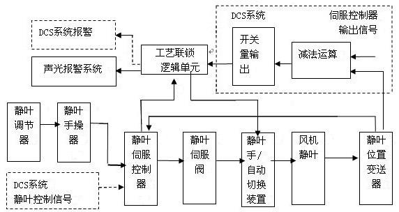
Manual/automatic switching device for fan stator blades and process interlocking method for stator blades
A technology of process interlocking and automatic switching, applied in the direction of machine/engine, mechanical equipment, pump control, etc., can solve the problems of fan outlet air volume, violent fluctuation of wind pressure, imbalance of fan stator blades, affecting blast furnace production, etc.
- Summary
- Abstract
- Description
- Claims
- Application Information
AI Technical Summary
Problems solved by technology
Method used
Image

Examples
Embodiment Construction
[0047] In order to further explain the technical means and effects adopted by the present invention to achieve the intended purpose of the invention, below in conjunction with the accompanying drawings and preferred embodiments, the manual / automatic switching device for the stationary blade proposed according to the present invention and its participation in the interlocking process of the stationary blade of the fan The specific implementation of the method will be described in detail.
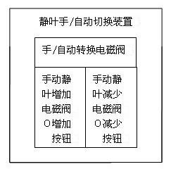
[0048] Such as figure 2 The schematic diagram of the manual / automatic switching device for stationary blades is shown. The manual / automatic switching device for fan static blades provided by the present invention includes: manual / automatic conversion solenoid valve, manual static blade increase solenoid valve, manual static blade increase button F, manual stator blade Decrease solenoid valve, manual vane reduction button G.
[0049] The input end of the manual / automatic conversion solenoid ...
PUM
 Abstract
Description
Claims
Application Information