An inner liquid-distributing hood type condensing heat exchange tube

一种换热管、内分液的技术,应用在换热器外壳、间接换热器、管状元件等方向,能够解决传热恶化等问题,达到消除液桥、提高传热效率的效果

Active Publication Date: 2011-12-14
NORTH CHINA ELECTRIC POWER UNIV (BAODING)
View PDF8 Cites 14 Cited by
  • Summary
  • Abstract
  • Description
  • Claims
  • Application Information

AI Technical Summary

Problems solved by technology

[0007] The purpose of the present invention is to change the separation of flow pattern and heat transfer in the traditional enhanced heat transfer method, solve the key problem that the thick liquid film is formed along the tube length direction in the condensation heat transfer, which makes the heat transfer worse, and provides a method different from the current one. The state-of-the-art internal liquid-distributing hood-type condensation heat exchange tube is based on the new idea of ​​regulating the condensation heat transfer flow pattern to improve the complete condensation heat transfer flow and heat transfer performance. It can start from the physical process of condensation, Starting from flow pattern control, fundamentally and greatly improve the efficiency of condensation phase change heat transfer

Method used


Image

  • An inner liquid-distributing hood type condensing heat exchange tube
  • An inner liquid-distributing hood type condensing heat exchange tube
  • An inner liquid-distributing hood type condensing heat exchange tube

Examples


Embodiment 1

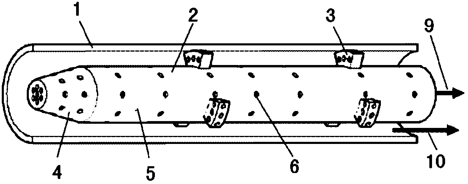
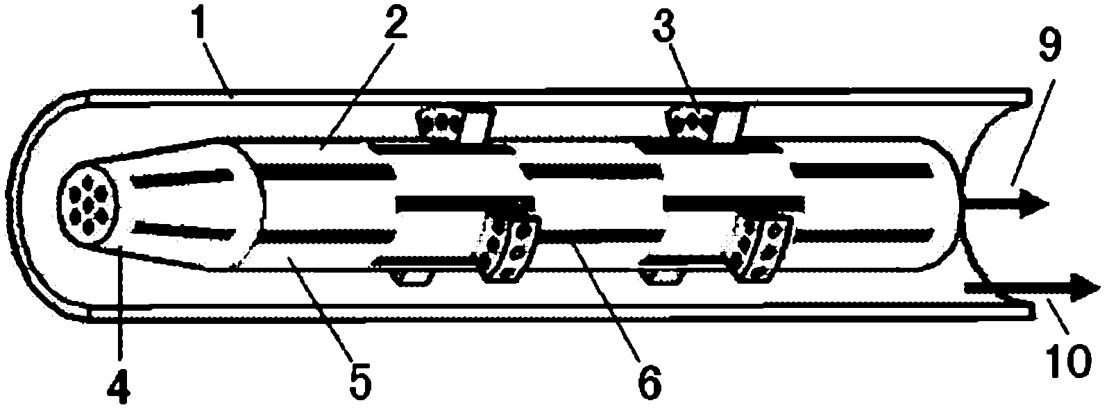
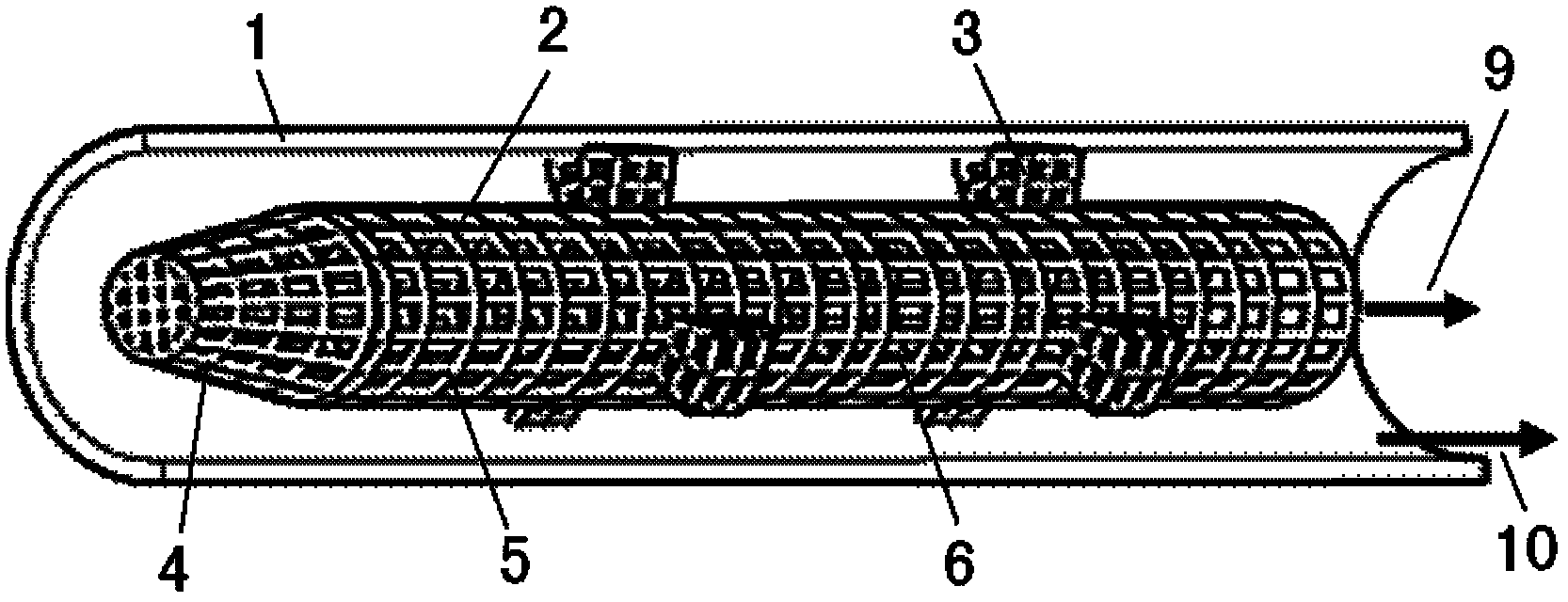
[0037] For the condensed water heat exchange process, a 50cm-long φ12mm×1mm ordinary smooth copper tube is selected as the outer heat exchange tube 1; a wire mesh with a mesh number of 14, a wire diameter of 0.4mm, and an aperture of 1.4mm is selected, and the length is 35cm, and the width is 1.4mm. Be the rectangular silk screen of 18.84mm (width is equal to 5 pipe circumferences of main distributing cover), roll into the cylindrical main dispensing cover 5 of inner liquid dispensing cover 2 of φ 6mm, long 35cm. Get the same screen, cut a trapezoidal roll to make the frustum-shaped drag-reducing cover 4 sides, and a circle as the drag-reducing cover 4 top cover. And cut a plurality of fan-shaped wire mesh to make a wire mesh structure support with a height of 2mm. Weld the drag reducing cover 4, the main liquid separating cover 5 and the wire mesh support 3 into one, and put them into the smooth outer heat exchange tube 1 to obtain an inner liquid separating cover type conden...


PUM


Abstract

The invention discloses an internal liquid-dividing hood-type condensed heat-exchanging pipe which can improve condensed phase change heat exchanging efficiency and belongs to the technical field of forced heat transfer. The condensed heat-exchanging pipe is formed by arranging an internal liquid-dividing hood with a microporous or seam structure inside a common external heat-exchanging pipe; condensed liquid formed in the heat-exchanging process flows through the micropore or the seam and is pumped and sucked into the liquid-dividing hood in time under the action of a liquid surface tension,so that the gas phase is separated from the liquid phase; the condensed liquid flows in the internal liquid-dividing hood and is drained out of the heat-exchanging pipe through the internal liquid-dividing hood; and steam is kept to flow in a clearance between the external heat-exchanging pipe and the internal liquid-dividing hood, so that the inner wall of the external heat-exchanging pipe contacts the steam to the maximum extent and a thin liquid film is formed on the inner wall surface of the external heat-exchanging pipe, and thus the condensed heat-exchanging coefficient is improved. Thetechnical problem that the heat transfer is deteriorated because a thick liquid film is formed in the direction of the pipe length in the condensed heat transfer process is fundamentally overcome; the internal liquid-dividing hood-type condensed heat-exchanging pipe is not affected by weight, so that the condensed heat transfer coefficient can be obviously improved on the ground and in a microgravity environment.

Description

technical field [0001] The invention belongs to the technical field of heat transfer enhancement, and relates to an internal liquid-distributing hood type condensation heat exchange tube for improving the thermal efficiency of condensation phase transformation in the tube. Background technique [0002] Condensing phase change heat exchangers (ie condensers) are widely used in refrigeration, air conditioning, power generation, petrochemical and other fields due to the high efficiency of phase change heat transfer. In some applications, such as using a low-grade heat source to drive the ORC cycle, it is necessary to reduce the temperature and pressure in the condenser in the Rankine cycle as much as possible, so that the condenser is in a small temperature difference (the temperature difference between the organic working medium in the tube and the air outside the tube or cooling water is small) Driven to work, resulting in an increase in heat transfer area and investment cost...

Claims


Application Information

Patent Timeline
Patent Type & Authority Applications(China)
IPC IPC(8): F28F1/00F28F9/00F28F13/04
CPCF28D15/025F28D15/046F28F9/013F28F1/10F28F9/00F28F13/04F28F1/00F28F1/16F28F1/426
Inventor 陈宏霞徐进良王伟
Owner NORTH CHINA ELECTRIC POWER UNIV (BAODING)
Why Eureka
Try Eureka