Grinding Drill for Robotic Assisted Cervical Disc Replacement Surgery System

A robot-assisted, cervical intervertebral disc technology, which is applied in surgery, medical science, etc., can solve the problems of grinding and drilling without using the cervical intervertebral disc replacement surgery system, and achieve the effects of compact structure, reduced deformation, and good grinding effect

Inactive Publication Date: 2011-12-21
HARBIN INST OF TECH
View PDF2 Cites 7 Cited by
  • Summary
  • Abstract
  • Description
  • Claims
  • Application Information

AI Technical Summary

Problems solved by technology

[0004] The existing grinding drill used in artificial cervical disc replacement surgery is a high-speed disc-shaped milling cutter, and the doctor uses the positioning frame to complete the grinding. The grinding drill has great limitations when it is applied to the robot-assisted cervical disc surgery system. There is no dedicated burr for robotic-assisted cervical disc replacement surgery systems

Method used


Image

  • Grinding Drill for Robotic Assisted Cervical Disc Replacement Surgery System
  • Grinding Drill for Robotic Assisted Cervical Disc Replacement Surgery System
  • Grinding Drill for Robotic Assisted Cervical Disc Replacement Surgery System

Examples


specific Embodiment approach 1

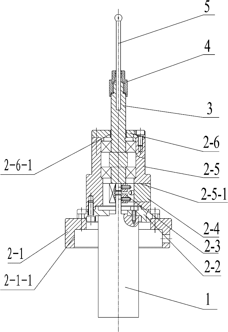
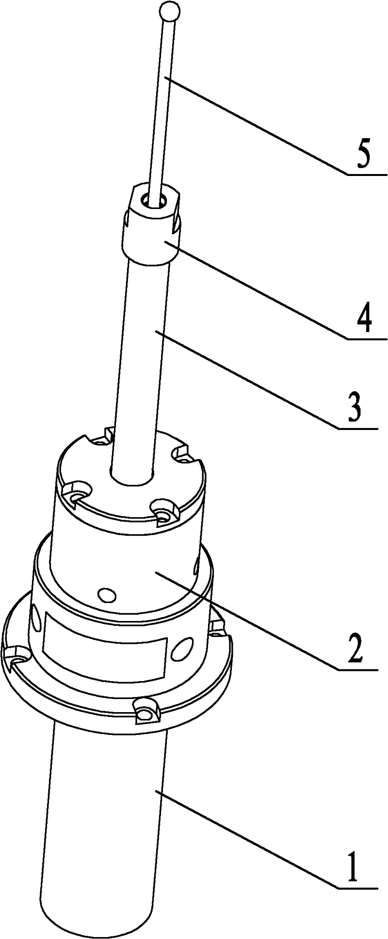
[0011] Specific implementation mode one: as Figure 1~2 As shown, the burr used in the robot-assisted cervical disc replacement surgery system of this embodiment includes a high-speed DC motor 1, a motor holder 2, a burr drive shaft 3 and a grinding head 5, and the motor holder 2 includes a connecting platform 2 -1, fixed ring 2-2, shaft coupling 2-3, housing 2-5 and end cover 2-6, one end of the fixed ring 2-2 passes through the output shaft of the high-speed DC motor 1 and is fixed On the end face of the output shaft end of the high-speed DC motor 1, the other end of the fixed ring 2-2 is fixed on the end face of the housing 2-5, and one end of the milling drive shaft 3 is mounted on the housing 2 through a bearing. -5, one end of the drill drive shaft 3 is affixed to the output shaft of the high-speed DC motor 1 through a coupling 2-3, and the grinding head 5 is fixed on the other end of the drill drive shaft 3, so A first central through hole 2-6-1 is processed in the axi...

specific Embodiment approach 2

[0012] Embodiment 2: The shaft coupling 2-3 in this embodiment is a diaphragm type high torque coupling. This design ensures the high efficiency of power transmission, eliminates the problem of axial eccentricity, and facilitates card installation. Other components and connections are the same as those in the first embodiment.

specific Embodiment approach 3

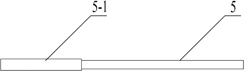
[0013] Specific implementation mode three: as image 3 As shown, the grinding end of the grinding head 5 is a cylindrical grinding head 5-1. With such a design, it can be used to grind the planes of the rostral and caudal endplates of the cervical spine. Other compositions and connections are the same as those in the first or second embodiment.


PUM


Abstract

A burr used in a robot-assisted cervical intervertebral disc replacement surgery system relates to a burr. The present invention solves the problem that there is no dedicated grinding drill for robot-assisted cervical intervertebral disc replacement surgery system at present. One end of the fixed ring passes through the output shaft of the high-speed DC motor and is fixed on the end face of the output shaft end of the high-speed DC motor, and the other end of the fixed ring is fixed on an end face of the housing. One end of the drive shaft is installed in the housing through a bearing, one end of the drive shaft of the grinder is fixedly connected to the output shaft of the high-speed DC motor through a coupling, the grinding head is fixed on the other end of the drive shaft of the grinder, and the end The cover is machined with a first central through hole in the axial direction, the end cover is fixed on the other end surface of the housing through the drive shaft of the mill drill, and the connecting platform is machined with a second central through hole in the axial direction, so The connecting platform passes through the high-speed DC motor and is fixedly connected with the fixed ring. The invention is a burr used in a robot-assisted cervical intervertebral disc replacement operation system.

Description

technical field [0001] The invention relates to a burr, in particular to a burr used in a robot-assisted cervical intervertebral disc replacement operation system. Background technique [0002] Compared with conventional anterior cervical decompression and fusion surgery, artificial cervical disc replacement has obvious advantages in the treatment of cervical spondylosis, but artificial cervical disc replacement is not widely carried out, mainly because of its complicated operation and difficult operation. It is difficult for most doctors to master, and the accuracy of the operation is not high, which affects the effect of the operation, and there are many surgical complications. The biggest difficulty in artificial cervical disc replacement surgery is the need to grind the bone mating surface that fits the prosthesis at the correct position to ensure the fit between the prosthesis and the human bone. The therapeutic effect depends heavily on the accuracy of the operation. ...

Claims


Application Information

Patent Timeline
Patent Type & Authority Applications(China)
IPC IPC(8): A61B17/16
Inventor 杜志江吴冬梅赵俊王伟东
Owner HARBIN INST OF TECH
Why Eureka
Try Eureka