Device and method for improving measurement accuracy and symmetry of polarization-maintaining fiber polarization coupling

A coupling measurement and polarization-maintaining optical fiber technology, which is applied in the direction of measuring devices, testing optical performance, instruments, etc., can solve the problems of envelope broadening and interference peak reduction, affecting measurement accuracy, reducing the spatial resolution of polarization mode coupling, etc., and achieves the best results Significant, obvious effect, simple structure effect

Active Publication Date: 2011-12-21
HARBIN ENG UNIV
View PDF6 Cites 33 Cited by
  • Summary
  • Abstract
  • Description
  • Claims
  • Application Information

AI Technical Summary

Problems solved by technology

Research shows: (Tianhua Xu, Wencai Jing, Hongxia Zhang, et.al.Influence of birefringence dispersion on a distributed stress sensor using birefringent optical fiber, Optical Fiber Technology, Volume 15, Issue 1, January 2009, Pages 83-89, and Feng Tang , Xiang-zhao Wang, Yimo Zhang, Wencai Jing, Influence of birefringence dispersion on distributed measurement of polarization coupling in birefringent fibers, Opt.Eng., Vol.46, 075006(2007)) Birefringence dispersion has envelope broadening on white light interference signal and interference peak decrease, which reduces the spatial resolution of the polarization mode coupling and also reduces the detection sensitivity of the coupling strength
And the influence of birefringence dispersion

Method used


Image

  • Device and method for improving measurement accuracy and symmetry of polarization-maintaining fiber polarization coupling
  • Device and method for improving measurement accuracy and symmetry of polarization-maintaining fiber polarization coupling
  • Device and method for improving measurement accuracy and symmetry of polarization-maintaining fiber polarization coupling

Examples


Example Embodiment

Specific implementation mode one:

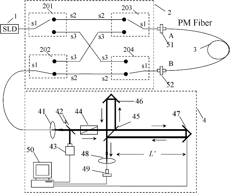
[0037] like figure 2 shown. The optical signal controllable reversing mechanism 2 is composed of four 1×2 polarization-maintaining optical switches to realize cross transposition of light. The common terminals s1 of the polarization maintaining switches 201 and 202 are respectively connected to the broadband light source 1 and the polarization coupling detection system 4, and the common terminals s1 of the polarization maintaining switches 203 and 204 are connected to the front end A of the optical fiber 3 to be tested through the rotary connectors 51 and 52 respectively. It is connected to the rear end B; the constant terminals s2 of the polarization maintaining switches 201-204 are connected to each other, and the action terminals s3 are cross-connected. Without loss of generality, if it is required to measure the polarization coupling of polarization-maintaining fiber at 1550nm wavelength, the wide-spectrum light source should be SLD, t...

Example Embodiment

Specific implementation mode two:

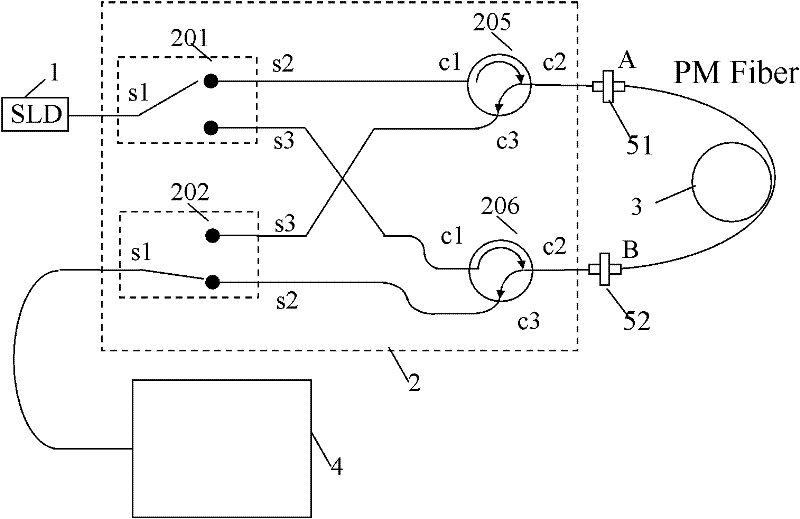
[0039] like image 3 shown. The composition of optical signal controllable reversing mechanism 2 can also be figure 2 The two 1×2 fiber optic switches in replace the three-port fiber optic circulator.

[0040] like image 3 shown. The optical signal controllable reversing mechanism 2 is composed of four 1×2 polarization-maintaining optical switches to realize cross transposition of light. The common terminals s1 of the polarization maintaining switches 201 and 202 are respectively connected to the broadband light source 1 and the polarization coupling detection system 4, and the output terminals c2 of the three-port circulators 205 and 206 are respectively connected to the front end A and the rear end B of the optical fiber 3 to be tested; The normally connected terminal s2 and the operating terminal s3 of the polarization maintaining switch 201 are respectively connected to the input terminals c1 of the circulators 205 and 206, and the...


PUM


Abstract

The invention provides a device and a method for improving the polarization-maintaining optical fiber polarization coupling measurement precision and the symmetry. The device comprises a wide-spectrum light source, a light signal controllable reversing mechanism, an optical fiber to be measured and a polarization coupling detection system, wherein the optical fiber to be measured is respectively connected between the wide-spectrum light source and the polarization coupling detection system in positive and opposite directions through the light signal controllable reversing mechanism, after low-coherence light emitted by the wide-spectrum light source enters the optical fiber to be measured through the light signal controllable reversing mechanism, transmission light and coupling light generated by the transmission light respectively enter the polarization coupling detection system, and the polarization-maintaining optical fiber polarization coupling point positions and amplitude information and the length of the optical fiber to be measured are obtained through calculating the signal amplitude and the scanning position of white light interference signals of the transmission light and the coupling light obtained in the polarization coupling detection system. The device and the method have very important practical value on the parameter measurement and the performance evaluation of optical fiber gyro sensitive rings and can also be widely applied to distributive polarization-maintaining optical fiber sensing systems.

Description

technical field [0001] The invention relates to a measuring device for polarization-maintaining optical fiber polarization coupling, in particular to a device and method for improving measurement accuracy and symmetry of polarization-maintaining optical fiber polarization coupling. Background technique [0002] Polarization-maintaining fiber is a kind of fiber waveguide with special functions, which refers to the fiber that can keep the original polarization state unchanged during the transmission process in the fiber after a polarization mode is excited. In the interferometric optical fiber sensing technology, the use of polarization-maintaining optical fiber can overcome the influence of the external environment on the polarization state of the transmitted light wave in the optical fiber, and suppress the polarization fading phenomenon caused by interferometric measurement. Especially in some high-precision fiber optic sensors, such as fiber optic gyroscopes, fiber optic h...

Claims


Application Information

Patent Timeline
IPC IPC(8): G01M11/02G01C25/00
Inventor 杨军苑立波
Owner HARBIN ENG UNIV
Why Eureka
Try Eureka