
Unpowered drinking water purification equipment and purification process

A technology of purification equipment and purification process, which is applied in the direction of osmosis/dialysis water/sewage treatment, etc. It can solve the problems of increased cost, small water flow, small average filter pore size, etc., and achieve cost saving, easy transportation, and light weight.

Inactive Publication Date: 2011-12-28
TIANJIN WATER IND ENG EQUIP +1
View PDF1 Cites 4 Cited by
  • Summary
  • Abstract
  • Description
  • Claims
  • Application Information

AI Technical Summary

Problems solved by technology

[0004] Hollow fiber microfiltration membrane filtration in the prior art is to place multi-layer hollow fiber microfiltration membrane filaments in the filter, and use the micropores on the hollow fiber microfiltration membrane filaments to filter and purify water. Most of the membrane filaments are produced with polyvinylidene fluoride (PVDF) as the raw material. The existing production equipment process and formula determine that the average filtration pore size of the hollow fiber microfiltration membrane filament is 0.22 microns, and there are poor mechanical strength and deviation of the average filtration pore diameter. Small, low filtration speed, and small water flow; in order to increase water flow, pumps are usually used together, resulting in increased cost and poor mobility

Method used


Image

  • Unpowered drinking water purification equipment and purification process
  • Unpowered drinking water purification equipment and purification process
  • Unpowered drinking water purification equipment and purification process

Examples


Embodiment Construction

[0017] Embodiments of the present invention will be further described below in conjunction with the accompanying drawings.

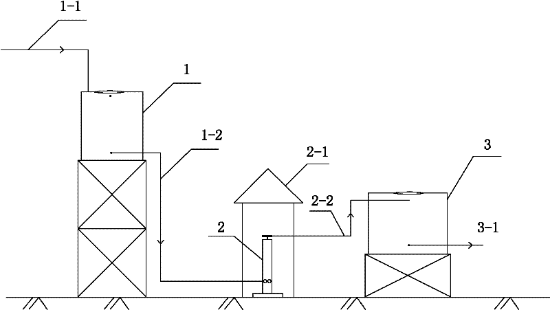
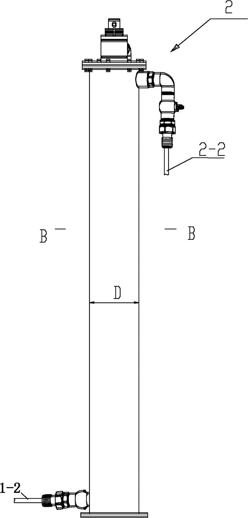
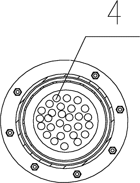
[0018] figure 1 It is a schematic diagram of equipment connection of the present invention; figure 2 yes figure 1 Schematic diagram of the structure of the water purifier; image 3 yes figure 2 Middle B-B sectional view; Figure 4 yes image 3 Schematic diagram of the membrane filament structure of a hollow fiber microfiltration membrane.

[0019] As shown in the figure, the present invention provides a kind of unpowered drinking water purification equipment. The unpowered drinking water purification equipment includes: a raw water tank 1, a water purifier 2 and a water production tank 3 connected in series in sequence; The upper part of the raw water tank 1 is provided with a raw water pipe 1-1 for water inlet, and the lower part of the raw water tank 1 is provided with a raw water outlet pipe 1-2; the raw water outlet pipe 1-2 is connected to t...


PUM


Abstract

The invention discloses a non-powered drinking water purification equipment and purification process. The purification equipment comprises: a raw water tank, a water purifier and a water production tank connected in series in sequence; the raw water tank is located above the water purifier and the water production tank; the upper part of the raw water tank is arranged There is a raw water pipe for water inlet, and a raw water outlet pipe is provided at the lower part of the raw water tank; the raw water outlet pipe is connected to the water inlet of the water purifier, and the water outlet of the water purifier is connected to the water purifier outlet pipe; the water purifier outlet pipe is connected to the upper part of the produced water tank The water inlet and the outlet pipe at the lower part of the produced water tank are drinking water outlets; the purification process is carried out in the following stages: raw water collection stage; filtration purification stage; water storage stage. The beneficial effects of the present invention are: saving cost; under the same pressure, the water production of each hollow fiber microfiltration membrane is increased by 200%-300% compared with the prior art, realizing stable water production under gravity; pollution-resistant and convenient for transportation; It is widely used for water supply in mountainous areas or rural areas without tap water supply, places where natural disasters occur, and emergency water supply for field operations.

Description

technical field [0001] The present invention relates to drinking water purification equipment and process, in particular to a non-powered drinking water purification equipment and purification process. Background technique [0002] Drinking water purification equipment in the prior art is a common equipment in people's daily life, and drinking water purification equipment usually adopts hollow fiber membrane technology. Hollow fiber membrane technology has the characteristics of simple principle, convenient operation, no adverse by-products, and no increase in pollution load to the external environment. With the general pollution of drinking water sources in my country and the continuous improvement of drinking water quality standards, membrane Technology has been transferred from the industrial water treatment industry to the field of drinking water purification. [0003] However, the use of hollow fiber membrane technology to purify water also has the following shortcomin...

Claims


Application Information

Patent Timeline
IPC IPC(8): C02F1/44
Inventor 张大群
Owner TIANJIN WATER IND ENG EQUIP
Learn More