Manufacturing method of electric excavator device
An electric excavator, technology of manufacturing method, applied to mechanically driven excavator/dredger, earth mover/shovel, construction, etc., can solve the problems of air pollution, environmental protection, high energy consumption of excavators, etc.
- Summary
- Abstract
- Description
- Claims
- Application Information
AI Technical Summary
Problems solved by technology
Method used
Image
Examples
Embodiment 1
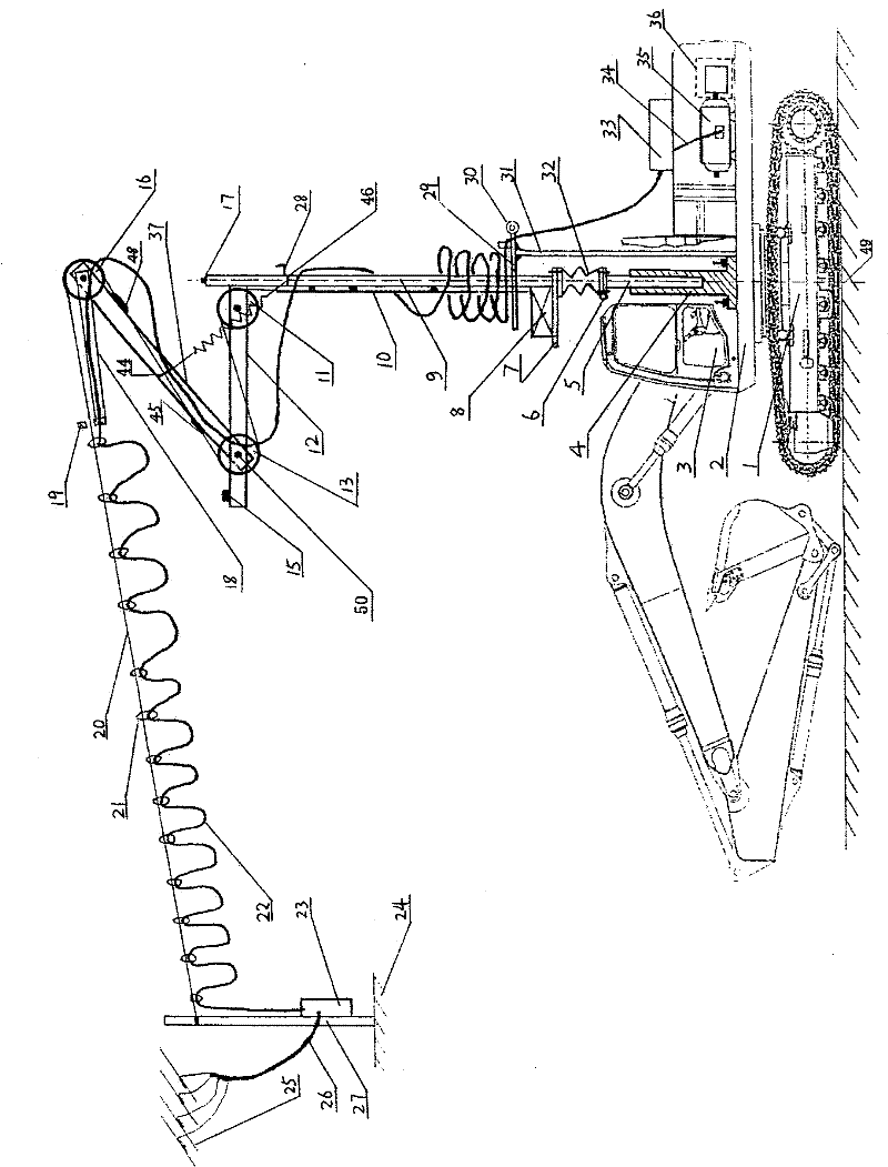
[0028] Embodiment 1: in combination with figure 1 , is a structural representation of the present invention. The manufacturing method of the electric excavator device of the present invention is composed of a basic vehicle body unit, a vehicle-mounted utility pole unit, a vehicle-mounted motor unit, a static vehicle body moving unit and a power supply unit.
[0029] The basic car body unit is composed of a lower car body part (1), a slewing platform (2) and an upper car body part (3), and the connection mode of the original excavator is maintained between them. The upper body part (3) is the remaining parts after the upper body of the original excavator is removed from all its fuel power and corresponding accessories, and the lower body part (1) and the rotary platform (2) are the original parts of the original body. Accessories.
[0030] The vehicle-mounted utility pole unit is composed of a hollow base (4), a lower pole (5), a spring assembly (32), a small winch (8), an up...
Embodiment 2
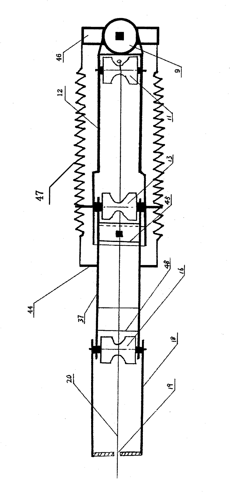
[0031] Embodiment 2: in combination with figure 2 , is a schematic diagram of the structure of the pulley assembly of the present invention. It consists of fixed pulley (11), central fixed pulley (13), tension fixed pulley (16), fixed fixed frame (12), swing fixed frame (37), free type fixed frame (18), tension spring (47) COMPOSITION. One end of the fixed mount (12) is connected to the fixed pulley (11), and this end is vertically fixed on the upper end of the upper support rod (9), and the other end is connected to the central fixed pulley (13) and the swing type through the movable shaft (50). One end of fixed mount (37). The other end of swing type fixed mount (37) connects tension fixed pulley (16) and an end of free type fixed mount (18) by rod shaft. The other end of freestyle fixed mount (18) connects the baffle plate (19) with aperture.
[0032] The two ends of tension spring (47) are respectively connected with the fixed plate (46) on the upper pole (9,) top and...
Embodiment 3
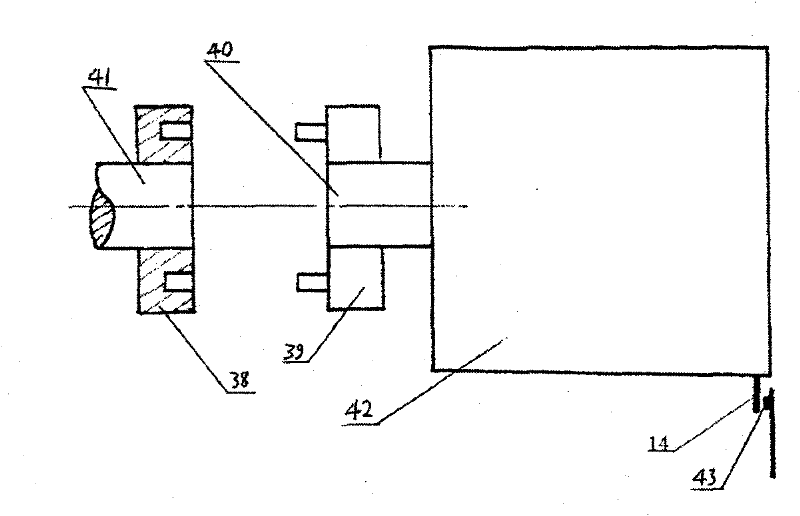
[0036] Embodiment 3, in conjunction with attached image 3, is a schematic diagram of the structure of the moving unit of the static car body of the present invention. Static car body mobile unit (36) is made of concave connection plate (38), convex connection plate (39), worm gear reducer (42) with small-sized motor, circuit switch (43) and small baffle plate (14). The concave connection plate (38) is fixed on the power shaft (41) right end of the motor (35), that is, the non-output end, and the convex connection plate (39) is fixed on the output shaft (40) of the worm reducer (42). The output shaft (40) of the speed reducer (42) is concentric with the power shaft (41) of the electric motor (35). When the car body needs to move temporarily, lock the worm reducer (42) in a position where the convex connection plate (39) and the concave connection plate (38) can be completely connected, otherwise lock it in a completely separated position, that is, the worm reducer Small baff...
PUM
 Abstract
Description
Claims
Application Information
 - R&D
- Intellectual Property
- Life Sciences
- Materials
- Tech Scout
- Unparalleled Data Quality
- Higher Quality Content
- 60% Fewer Hallucinations
Browse by: Latest US Patents, China's latest patents, Technical Efficacy Thesaurus, Application Domain, Technology Topic, Popular Technical Reports.
© 2025 PatSnap. All rights reserved.Legal|Privacy policy|Modern Slavery Act Transparency Statement|Sitemap|About US| Contact US: help@patsnap.com


