Spring fatigue test device for continuous impact of high-pressure gas
A high-pressure gas, fatigue test technology, applied in the direction of impact test, measuring device, machine/structural component test, etc., can solve the problem that the spring deformation process cannot be truly simulated, and achieve simple structure, convenient operation and wide test range Effect
- Summary
- Abstract
- Description
- Claims
- Application Information
AI Technical Summary
Problems solved by technology
Method used
Image

Examples
Embodiment 1
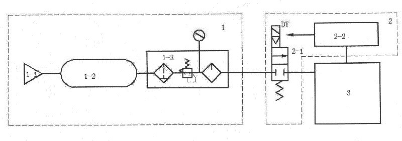
[0027] Such as Figure 1~4 As shown, a high-pressure gas continuous impact spring fatigue test device mainly includes a high-pressure gas power part 1, an electrical control part 2 and a mechanical part 3. Its characteristics are:
[0028] The high-pressure gas power part 1 is mainly composed of three parts: an air compressor 1-1, an air storage tank 1-2 and a pneumatic triple unit 1-3 (ie, an air filter, a pressure reducing valve and a lubricator). The air compressor 1-1 communicates with the air storage tank 1-2 through the air pipe, and is used to transport the high-pressure gas compressed by the air compressor 1-1 to the air storage tank 1-2 for storage, so as to realize gas supply and utilization. The balance of gas provides continuous and stable power for the device of the present invention. The air storage tank 1-2 communicates with the inlet port of the electromagnetic reversing valve 2-1 of the electrical control part 2 through the air pipe in turn through the pneum...
Embodiment 2
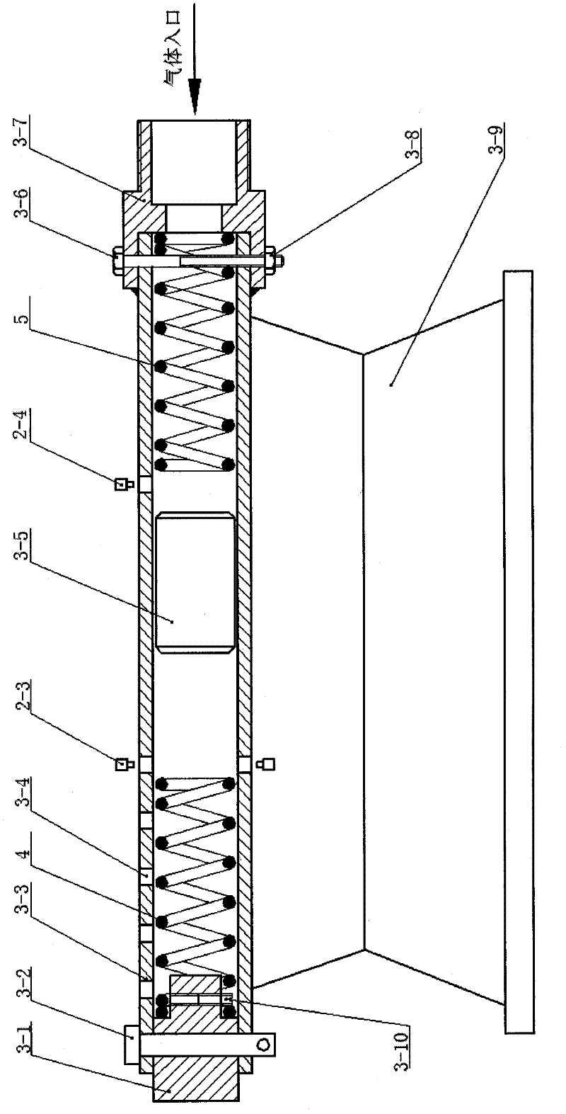
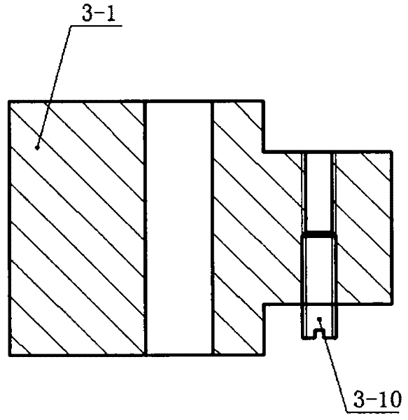
[0032] A spring fatigue test device continuously impacted by high-pressure gas, same as embodiment 1. Wherein: the length of the test tube 3-3 is 1000mm, the inner diameter is 15mm, and the wall thickness is 2mm; 25mm, wall thickness 2mm, the diameter of the air inlet hole at the boss in the big end of the pipe connector 3-7 is 8mm, the length of the mass block 3-5 is 50mm, and the elastic positioning The large end of the column 3-1 is 40mm long, and the small end is 15mm long. The diameter of the threaded through hole on the small end of the spring positioning column 3-1 is 4mm. The test tube 3-3 corresponds to the The diameter of the holes at the free ends of the test spring 4 and the auxiliary spring 5 is 8mm, and the number of the vent holes is 3, and the diameter is 8mm.
Embodiment 3
[0034] A spring fatigue test device continuously impacted by high-pressure gas, same as embodiment 1. Wherein: the length of the test tube 3-3 is 3000mm, the inner diameter is 70mm, and the wall thickness is 8mm; 100mm, wall thickness 8mm, the diameter of the air inlet hole at the boss in the big end of the pipe connector 3-7 is 50mm, the length of the mass block 3-5 is 200mm, and the elastic positioning The large end of the column 3-1 is 130mm long, and the small end is 40mm long. The diameter of the threaded through hole on the small end of the spring positioning column 3-1 is 10mm. The test tube 3-3 corresponds to The diameter of the holes at the free ends of the test spring 4 and the auxiliary spring 5 is 12 mm, and the number of the vent holes is 6 with a diameter of 12 mm.
PUM
| Property | Measurement | Unit |
|---|---|---|
| thickness | aaaaa | aaaaa |
| thickness | aaaaa | aaaaa |
| thickness | aaaaa | aaaaa |
Abstract
Description
Claims
Application Information
 - R&D
- Intellectual Property
- Life Sciences
- Materials
- Tech Scout
- Unparalleled Data Quality
- Higher Quality Content
- 60% Fewer Hallucinations
Browse by: Latest US Patents, China's latest patents, Technical Efficacy Thesaurus, Application Domain, Technology Topic, Popular Technical Reports.
© 2025 PatSnap. All rights reserved.Legal|Privacy policy|Modern Slavery Act Transparency Statement|Sitemap|About US| Contact US: help@patsnap.com