
A new phase difference detection circuit and method

A technology of phase difference detection and phase shifting circuit, applied in the direction of measuring electrical variables, phase angle between voltage and current, measuring devices, etc., can solve complex problems

Inactive Publication Date: 2011-12-28
INST OF FLUID PHYSICS CHINA ACAD OF ENG PHYSICS
View PDF5 Cites 9 Cited by
  • Summary
  • Abstract
  • Description
  • Claims
  • Application Information

AI Technical Summary

Problems solved by technology

[0004] The purpose of the present invention is to solve the problem that the method of detecting the phase difference and the phase lead or lag relationship in the prior art is too complicated, and provide a new phase difference detection circuit and method to accurately detect the phase difference and the lead lag relationship of two input signals , the detection circuit is simple and reliable

Method used


Image

  • A new phase difference detection circuit and method
  • A new phase difference detection circuit and method
  • A new phase difference detection circuit and method

Examples


Embodiment Construction

[0029] In order to make the object, technical solution and advantages of the present invention clearer, the present invention will be further described in detail below in conjunction with the accompanying drawings and embodiments. It should be understood that the specific embodiments described here are only used to explain the present invention, not to limit the present invention.

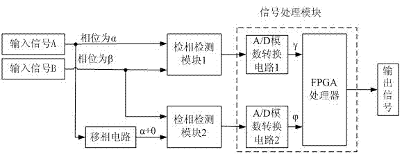
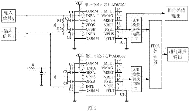
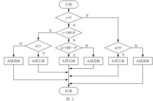
[0030] Design ideas: such as figure 1 As shown, the phase detection module 1 can directly detect the magnitude of the phase difference between the two input signals A and B, and its range is 0° to 180°. By adding a phase detection module 2 with the same function and a phase shifting circuit, The A / D module converts the output signal voltage value of the two phase detection modules into a digital signal and sends it to the FPGA (or a microprocessor with A / D conversion function, etc.), and the FPGA judges the phase difference of the two signals through a specific algorithm value and the lead-lag rel...


PUM


Abstract

The invention relates to a phase difference detection circuit and a method thereof in the signal detection field, and especially relates to a phase difference detection circuit which detects phase difference of two signals and an ahead or lagged relation of phases and a method thereof. A purpose of the present invention is to solve a problem that in the prior art detection of phase difference andan ahead or lagged relation of phases are too complex. The novel phase difference detection circuit and the method thereof are provided to accurately detect the phase difference of two signals and the ahead or lagged relation. The detection circuit is simple and reliable. A technical scheme of the invention is as follows: the detection circuit comprises a phase detection module 1, a phase detection module 2, an A / D analog to digital conversion circuit 1, an A / D analog to digital conversion circuit 2 and an FPGA processor. The invention mainly is applied to detection of phase difference of twosine waves or square wave signals and an ahead or lagged relation.

Description

technical field [0001] The invention relates to a phase difference detection circuit and method in the field of signal detection, in particular to a phase difference detection circuit and method for detecting the magnitude of the phase difference and the leading or lagging relationship between two signals. Background technique [0002] In the field of signal detection, it is often necessary to detect the phase difference between two signals, and the phase difference includes the magnitude of the phase difference and the leading or lagging relationship of the phase. A general phase detection chip (such as AD8302, etc.) can measure the phase difference of two signals, and its range is 0°~180°, but it cannot measure whether the phase difference of two signals is between 0°~+180° or 0°. °~-180° range, so it is impossible to judge the leading or lagging relationship of the phases of the two signals. [0003] "China Test" published an article entitled "Dual Longitudinal Mode Dual...

Claims


Application Information

Patent Timeline
IPC IPC(8): G01R25/00
Inventor 丁明军贾兴黄雷任青毅曹科峰张振涛叶超代刚黄斌马成刚龙燕邓明海曹宁翔冯宗明赵娟李玺钦于治国梁川马勋马军邓维军李亚维吴红光冯莉李巨李晏敏王浩王卫谢敏
Owner INST OF FLUID PHYSICS CHINA ACAD OF ENG PHYSICS
Learn More