
Overvoltage protection element and manufacturing method thereof

A technology for protection components and manufacturing methods, applied in the direction of overvoltage protection resistors, resistance manufacturing, electrical components, etc., can solve problems such as high trigger voltage, reduced conductivity, poor conductivity, etc., to reduce trigger voltage and improve conductance generality, the effect of enhancing the protective effect

Active Publication Date: 2011-12-28
YAGEO CORP
View PDF2 Cites 0 Cited by
  • Summary
  • Abstract
  • Description
  • Claims
  • Application Information

AI Technical Summary

Problems solved by technology

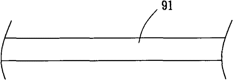
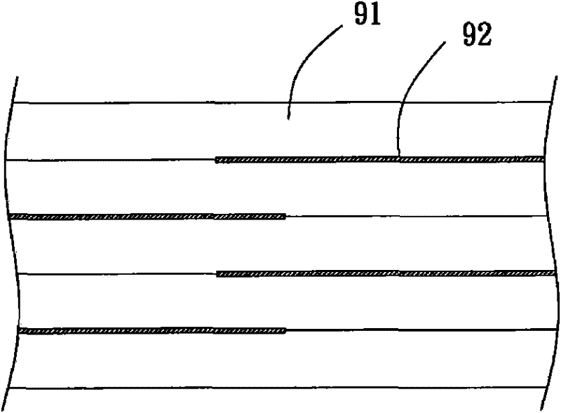
[0005] However, the above-mentioned existing multilayer overvoltage protection device still has the following disadvantages: for example, if zinc oxide (ZnO) is used as the material of the strip 91 doping part of the metal oxide and the binder, it will make the strip 91 The dielectric coefficient of 91 is too high, resulting in a high capacitance value of the aforementioned existing multilayer overvoltage protection components, and the overall capacitance value cannot be lower than 1pF
[0013] However, in the No. 469188 invention patent, since the driving layer is made of metal oxide ceramic powder with a core-shell structure, the electrical conductivity is not good, and the driving layer is a porous structure, so that the metal oxide ceramic powder There are gaps in the interval, which further reduces the overall conductivity, resulting in a high trigger voltage of the overvoltage protection element, which can reach more than 300V, so it also has the disadvantage of poor protection effect on circuit elements
[0014] Based on the above reasons, because the above-mentioned existing overvoltage protection elements usually use metal oxides, silicon carbide or low dielectric constant materials as the driving layer, it causes the disadvantage of high trigger voltage; moreover, if the If the metal oxide is mixed with a binder or a bonding agent and baked above 850°C to make the driving layer, the binder or bonding agent will be volatilized due to the high-temperature process and cannot exist in the driving layer, so that the driving layer will be The formation of a porous structure causes an increase in trigger voltage

Method used


Image

  • Overvoltage protection element and manufacturing method thereof
  • Overvoltage protection element and manufacturing method thereof
  • Overvoltage protection element and manufacturing method thereof

Examples


Embodiment Construction

[0050] In order to make the above and other objects, features and advantages of the present invention more obvious and understandable, the following is a detailed description of the preferred embodiments of the present invention in conjunction with the accompanying drawings:

[0051] Please refer to Picture 10 As shown, the overvoltage protection element of the preferred embodiment of the present invention includes a substrate 1, two electrodes 2 and a driving layer 3.

[0052] The substrate 1 of the present invention can be selected as a glass substrate, a ceramic substrate or a substrate made of other materials.

[0053] The two electrodes 2 of the present invention are arranged on the surface of the substrate 1. The electrodes 2 are preferably made of materials with better conductivity, such as platinum (Pt), silver (Ag), or copper (Cu), etc. . A distance w is formed between the two electrodes 2, and the distance w can be adjusted according to the trigger voltage required by the...


PUM

PropertyMeasurementUnit
The average particle sizeaaaaaaaaaa
Thicknessaaaaaaaaaa

Abstract

The invention relates to an OVP (over voltage protection) element and a manufacturing method thereof. The OVP element comprises a substrate, two electrodes and a driver layer, wherein the two electrodes are arranged on one surface of the substrate; and the driver layer is electrically connected with the two electrodes and formed by metals, magnetic metallic oxides and a binding agent. The manufacturing method of the OVP element comprises the following steps: forming the two electrodes on the surface of the substrate; printing inks containing the metals, the magnetic metallic oxides and the binding agent on the surface of the substrate, thus the two electrodes are connected to form an ink layer; and baking the substrate at the temperature of 150-400 DEG C, thus the ink layer is solidified to form the driver layer. According to the OVP element and the manufacturing method thereof, the electrical conductivity of the driver layer of the OVP element can be reduced, and a porous structure is prevented from being formed on the driver layer.

Description

Technical field [0001] The invention relates to a protection element and a manufacturing method thereof, in particular to an overvoltage protection element and a manufacturing method thereof. Background technique [0002] Generally speaking, surges have strong instantaneous energy, and electronic devices in circuits usually cannot withstand the impact of high-energy surges. In order to avoid damage to electronic equipment due to surge impact, an over-voltage protection element is usually installed in the circuit to filter out the surge. The overvoltage protection components are usually divided into two types: multilayer and single-layer. [0003] Please refer to figure 1 As shown, the existing manufacturing method of multi-layered overvoltage protection element usually firstly uses zinc oxide (ZnO) or silicon carbide (SiC) as the main body, and then doped some metal oxides and binders (binder) together to manufacture Into a thin strip 91; figure 2 As shown, internal electrodes 9...

Claims


Application Information

Patent Timeline
IPC IPC(8): H01C7/12H01C17/00H01C17/065H02H9/04
Inventor 刘志顺曾敬源黄国桢李俊德苏哲仪李文熙
Owner YAGEO CORP
Learn More