
A kind of semiconductor device and its forming method

A semiconductor and device technology, applied in the field of semiconductor devices and their formation, can solve problems such as leakage

Active Publication Date: 2011-12-28
INST OF MICROELECTRONICS CHINESE ACAD OF SCI
View PDF4 Cites 5 Cited by
  • Summary
  • Abstract
  • Description
  • Claims
  • Application Information

AI Technical Summary

Problems solved by technology

[0003] However, if Figure 7 to Figure 9 As shown, it is found in practice that a gap 34 is formed at the junction of the source-drain region 32 and the isolation region 12; then, as Figure 10 to Figure 12 As shown, when the contact region 36 (such as a metal silicide layer) is subsequently formed on the source and drain regions 32, the contact region 36 can easily pass through the gap 34 to reach the junction region, thereby causing leakage

Method used


Image

  • A kind of semiconductor device and its forming method
  • A kind of semiconductor device and its forming method
  • A kind of semiconductor device and its forming method

Examples


Embodiment Construction

[0039] The disclosure below provides many different embodiments or examples for realizing the technical solution provided by the present invention. Although components and arrangements of specific examples are described below, they are examples only and are not intended to limit the invention.

[0040] Furthermore, the present invention may repeat reference numerals and / or letters in different embodiments. This repetition is for simplicity and clarity and does not in itself indicate a relationship between the various embodiments and / or arrangements discussed.

[0041] The present invention provides examples of various specific processes and / or materials, however, alternative applications of other processes and / or other materials that can be realized by those skilled in the art obviously do not depart from the scope of the present invention. It should be emphasized that the boundaries of various regions described in this document include necessary extensions due to process or ...


PUM


Abstract

The invention provides a forming method of a semiconductor device. The method is characterized in that a step of forming source / drain regions comprises the following substeps: determining a junction region and forming an auxiliary layer; with the auxiliary layer, a gate stack structure and isolation regions as masks, removing partial thickness of a semiconductor substrate in an active region to form a groove; and generating semiconductor materials in the groove to fill the groove, wherein the auxiliary layer covers the junction region; and the junction region comprises partial width of activeregion connected with the isolation regions. The invention also provides the semiconductor device. The semiconductor device is characterized in that semiconductor substrate materials are sandwiched between the source / drain regions and the isolation regions. The semiconductor device and the method are beneficial to leakage reduction.

Description

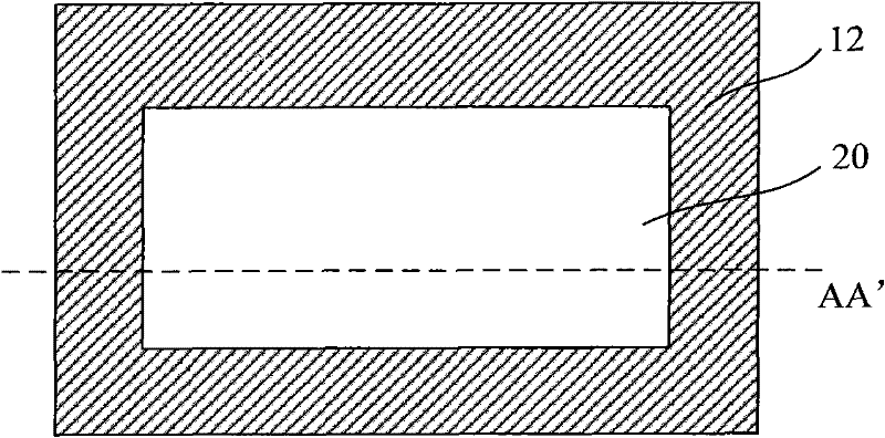
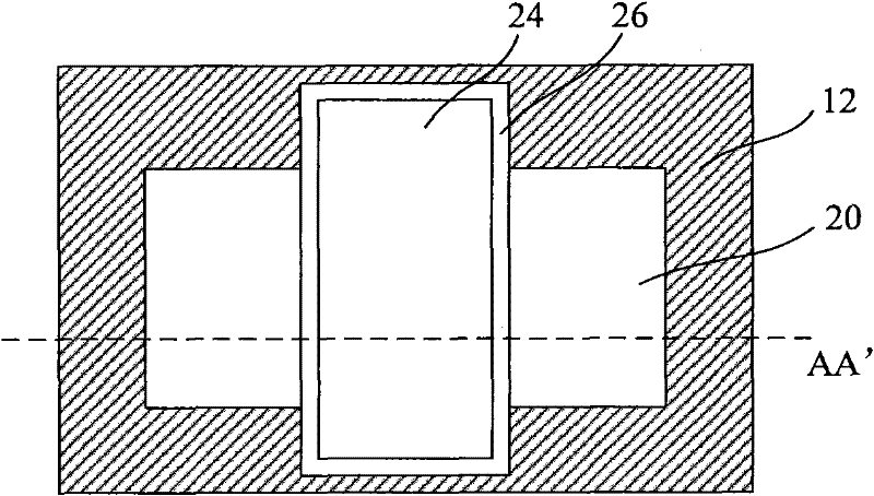
technical field [0001] The present invention relates to the technical field of semiconductors, in particular to a semiconductor device and a forming method thereof. Background technique [0002] Currently, methods for forming semiconductor devices include: first, as figure 1 and figure 2 As shown, an active region 20 and an isolation region 12 surrounding the active region 20 are formed on a semiconductor substrate 10; subsequently, as image 3 and Figure 4 As shown, a gate stack structure is formed (the gate stack structure includes a gate dielectric layer 22, a gate 24 formed on the gate dielectric layer 22 and sidewalls 26 surrounding the gate dielectric layer 22 and the gate 24 , in practice, a capping layer is also formed on the gate, and the capping layer is usually silicon nitride, which can prevent the gate from being damaged during operation. For the convenience of description, the text and drawings in this document , the capping layer is no longer marked), th...

Claims


Application Information

Patent Timeline
Patent Type & Authority Applications(China)
IPC IPC(8): H01L21/336H01L29/78H01L29/06H01L29/12
CPCH01L21/823807H01L21/823878H01L21/823814H01L29/66H01L29/78H01L29/7848H01L29/66636H01L21/8238
Inventor 尹海洲骆志炯朱慧珑
Owner INST OF MICROELECTRONICS CHINESE ACAD OF SCI
Learn More