
Method for manufacturing semiconductor device structure

A device structure and semiconductor technology, applied in the fields of semiconductor devices, semiconductor/solid-state device manufacturing, and electric solid-state devices, etc., can solve the problems of increased driving current of semiconductor device structures, lack of semiconductor devices, and large on-chip resistance, etc., to avoid Shadow effect, improved electrical performance, reduced drive current effect

Active Publication Date: 2013-04-10
SEMICON MFG INT (SHANGHAI) CORP +1
View PDF2 Cites 0 Cited by
  • Summary
  • Abstract
  • Description
  • Claims
  • Application Information

AI Technical Summary

Problems solved by technology

[0005] However, the problem in the process of preparing the S / D extension region of the PMOS region is that when the above-mentioned sidewall layer structure is removed, it is easy to cause damage to the silicide region above the epitaxial region, making the silicide region very thin and reducing the resistance of the silicide region. Very big
That is, the total resistance of the epitaxial region and the silicide region is much greater than the resistance of other parts of the structure. Correspondingly, problems similar to the above will also occur in the NMOS region of the semiconductor device structure, resulting in a larger on-chip resistance of the finally obtained semiconductor device structure. , further leading to an increase in the driving current of the semiconductor device structure
In addition, since in the prior art, the silicide region is formed first and then the LDD region is formed, it is also possible that during the preparation process of the LDD region, the ions in the LDD region cannot be accurately implanted into the layout design position, that is, during the preparation process of the LDD region It is easy to produce shadow effect, and then it is impossible to prepare the LDD area that meets the layout design, so that the semiconductor device structure that meets the actual process requirements cannot be obtained

Method used


Image

  • Method for manufacturing semiconductor device structure
  • Method for manufacturing semiconductor device structure
  • Method for manufacturing semiconductor device structure

Examples


Embodiment Construction

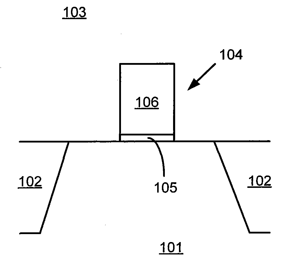
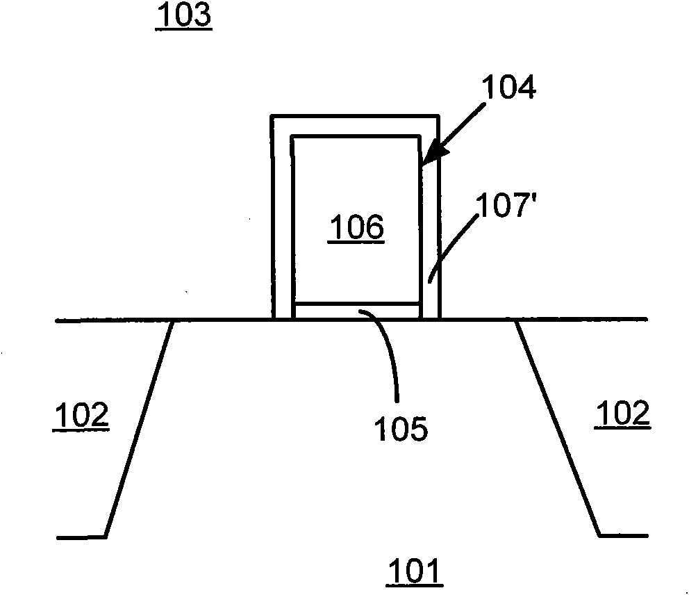
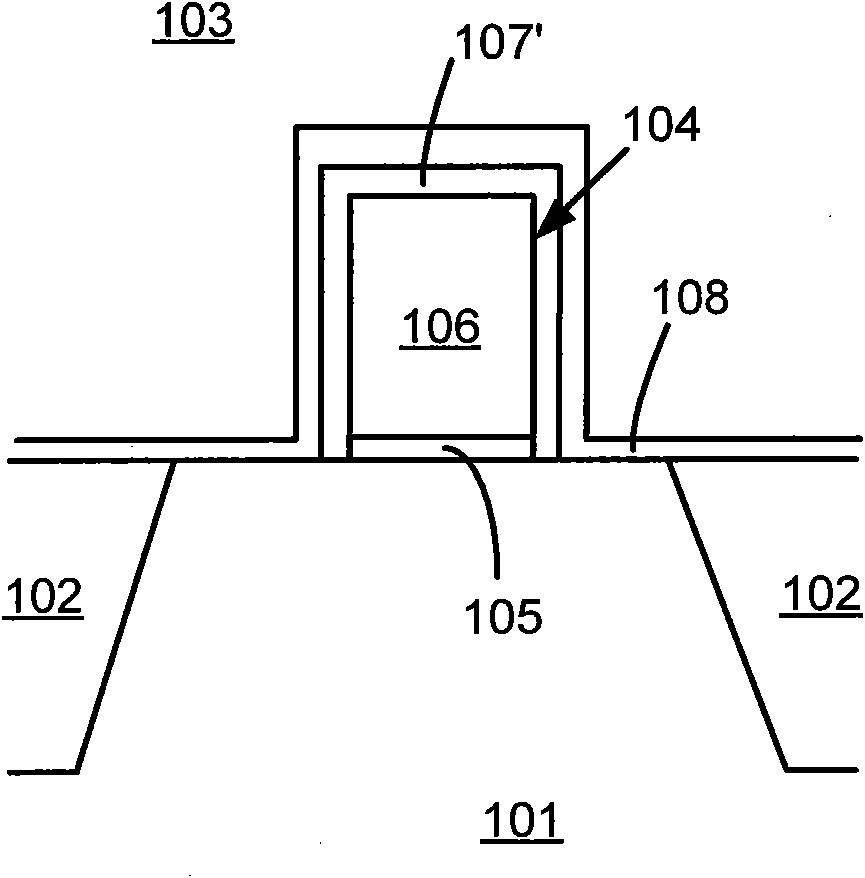
[0031] In the following description, numerous specific details are given in order to provide a more thorough understanding of the present invention. It will be apparent, however, to one skilled in the art that the present invention may be practiced without one or more of these details. In other examples, some technical features known in the art are not described in order to avoid confusion with the present invention.

[0032] In order to thoroughly understand the present invention, detailed steps will be presented in the following description, so as to explain how the present invention improves the process of fabricating semiconductor device structures to solve the problems in the prior art. Obviously, the practice of the invention is not limited to specific details familiar to those skilled in the semiconductor arts. Preferred embodiments of the present invention are described in detail below, however, the present invention may have other embodiments besides these detailed d...


PUM


Abstract

The invention discloses a method for manufacturing a semiconductor device structure, comprising the following steps: providing a substrate, wherein a grid structure is formed above the substrate; forming a gap wall structure comprising a first side wall layer structure and a first packing oxidization layer structure surrounding the grid structure; forming an epitaxial region on the substrate; removing the first side wall layer structure in the gap wall structure and forming a first offset side wall layer structure; forming a light dope region at a position which is located at the inner side of the epitaxial region in the substrate and adjacent to the epitaxial region, and forming a second side wall layer structure at an outer side of the first offset side wall layer structure; and forminga silicification region at the outer side of the second side wall layer structure above the epitaxial region and forming a source electrode / drain electrode in the substrate so as to obtain the semiconductor device structure. By using the method, the silicification region above the epitaxial region is not damaged, thus reducing the resistance of the silicification region and decreasing the resistance on chip of the semiconductor device structure, thereby improving the electrical performances of the manufactured semiconductor device structure.

Description

technical field [0001] The invention relates to a semiconductor manufacturing process, in particular to a method for manufacturing a semiconductor device structure. Background technique [0002] Driven by the miniaturization, high density, high speed, high reliability and system integration of semiconductor devices, the minimum feature size of semiconductor devices has also developed from the initial 1 mm to the current 90 nanometers or 60 nanometers, and in In the next few years, we will enter the era of 45nm and below nodes. If the composition and structure of semiconductor devices are not changed, simply scaling down semiconductor devices will become impossible due to their excessive saturation leakage current (IDSS). OK, so semiconductor devices will change the composition or structure of some components to reduce IDSS while scaling down. For example, the length of the channel region below the transistor gate can be adjusted to change the resistance of the combined chan...

Claims


Application Information

Patent Timeline
Patent Type & Authority Patents(China)
IPC IPC(8): H01L21/336H01L21/28H01L21/768H01L27/04
Inventor 何有丰胡亚兰
Owner SEMICON MFG INT (SHANGHAI) CORP
Learn More