Liquid cooling auto-excitation-type eddy current retarder without electric brush structure

An eddy current retarder and retarder technology, applied in the direction of electric brake/clutch, asynchronous inductive clutch/brake, motor, etc., can solve the problem of limiting the improvement of braking torque and continuous braking of self-excited retarder. Time, low life, inability to effectively dissipate the heat of the eddy current induction body of the retarder, etc., to achieve the effect of small braking torque recession, high reliability, and eliminating the need for brush devices

Inactive Publication Date: 2013-10-16
YANGZHOU ANXING ELECTROMECHANICAL TECH
View PDF3 Cites 3 Cited by
  • Summary
  • Abstract
  • Description
  • Claims
  • Application Information

AI Technical Summary

Problems solved by technology

[0004] Invention patent (patent application No. 201010516737.0) titled "a double-rotor disc self-excited retarder and its control method" and a utility model patent titled "vehicle retarder with self-generating power" (patent application No. The self-excited retarder disclosed in 201020205726.6) adopts air-cooled heat dissipation method, which cannot effectively dissipate the heat generated on the eddy current induction body of the retarder, which limits the improvement of the braking torque and continuous braking of the self-excited retarder. moving time
The invention patent titled "a self-excited retarder with a water cooling system" (patent application number 200810243194.2) discloses a self-excited retarder that uses water cooling to dissipate heat. Although it solves the problem of heat dissipation, the structure must There is a brush device to transmit the power on the generator stator armature to the rotating retarder rotor coil, so it has the disadvantage of low life

Method used


Image

  • Liquid cooling auto-excitation-type eddy current retarder without electric brush structure

Examples


Embodiment Construction

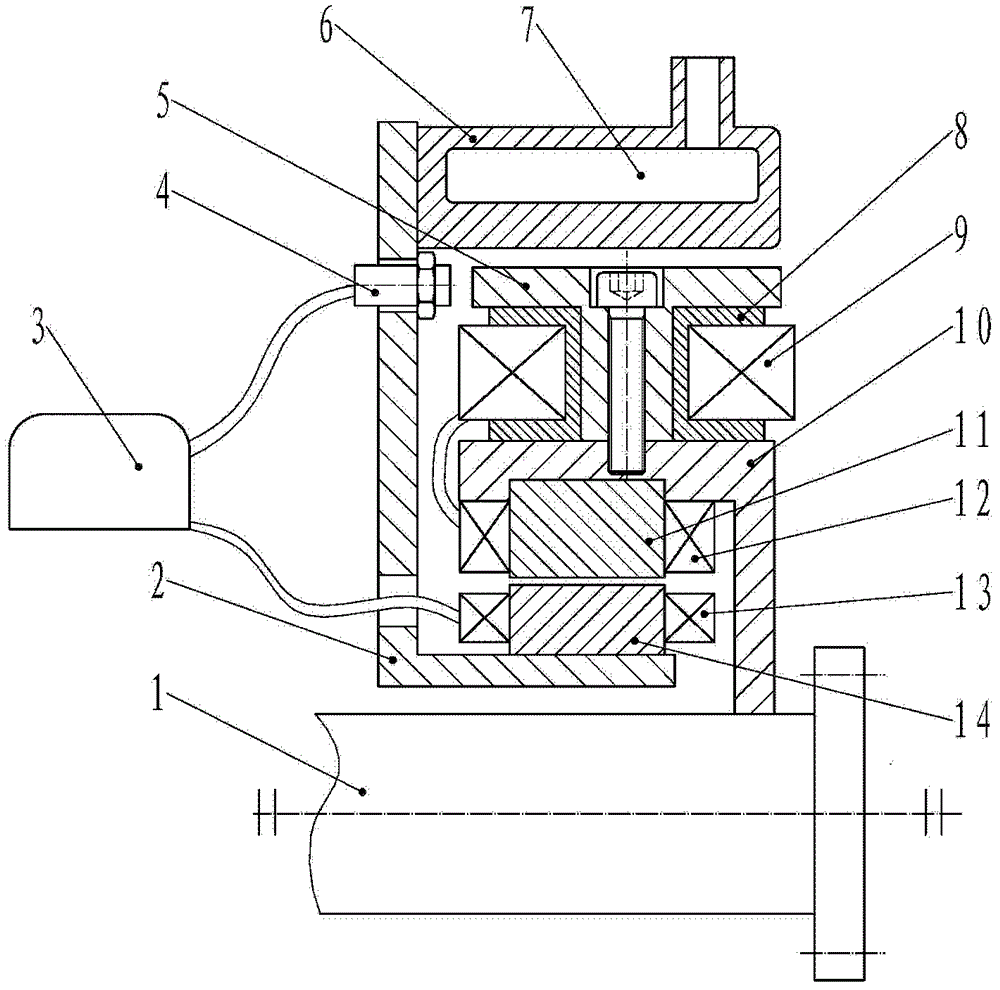
[0018] Specific embodiments of the present invention will be further described below in conjunction with the accompanying drawings.

[0019] like figure 1 As shown, the stator 6 of the retarder in the embodiment of the present invention is provided with a water channel 8, which is placed on the outermost side of the retarder. Both the retarder stator 6 and the speed sensor 5 are fixed on the retarder fixing frame 2, and the speed sensor 4 is used for measuring the speed of the retarder. The retarder coil 9 and the coil frame 8 are fixed in the electromagnet core 5, and 8-12 electromagnet cores 5 are evenly distributed on the outer circumference of the iron core holder 10, and the outer diameter of the electromagnet core 5 and the inner diameter of the stator water jacket 6 keep 0.5-1.5 mm clearance. The core holder 10 is fixed on the transmission shaft 1 and rotates together with the transmission shaft 1 . The generator armature iron core 11 is embedded in the inner ring of...


PUM


Abstract

A self-excited eddy current liquid-cooled retarder is disclosed. The retarder pertains to an auxiliary braking device retarding a vehicle, and comprises a retarder rotor, a retarder stator, a control module and a generator unit. The retarder rotor comprises a retarder coil, an electromagnet core and a core cage. The retarder coil is wound on a coil frame. The electromagnet core is inserted into the coil frame. The electromagnet core, the retarder coil and the coil frame are evenly distributed on the circumference of the core cage. The retarder rotor is connected to a transmission shaft of an automobile. The inner circle of the retarder stator and the outer circle of the electromagnet core of the retarder rotor are coaxial. The generator unit comprises a generator exciting winding, a generator exciting magnetic pole, a generator armature winding and a generator armature core and is received in the retarder rotor.

Description

technical field [0001] The invention relates to an automobile retarder, in particular to a self-excited eddy current retarder utilizing liquid cooling to dissipate heat, belonging to an auxiliary braking device for decelerating a vehicle. Background technique [0002] The retarder is a safety auxiliary device for driving brakes, which applies the braking force to the transmission parts of the vehicle to reduce the driving speed of the vehicle. At present, the most widely used retarder in our country is the eddy current retarder, which uses the principle of electromagnetism to convert the kinetic energy of the car into heat energy, and dissipates it through air cooling. The eddy current retarder can improve the braking performance of the car, eliminate the traditional braking noise and environmental pollution, prolong the service life of the brake pads and tires, and greatly improve the safety, comfort and economy of the car. Although the eddy current retarder has the advant...

Claims


Application Information

Patent Timeline
Patent Type & Authority Patents(China)
IPC IPC(8): H02K49/04H02K1/20B60L7/28B60L50/16
CPCH02K49/043B60L3/0076Y02T10/7241B60L7/14B60L2210/40Y02T10/641H02K1/20B60L7/28B60L2240/36H02K11/0094B60L11/14H02K9/19Y02T10/7077B60L2220/14B60L50/16Y02T10/64Y02T10/72Y02T10/7072Y02T10/70H02K5/203
Inventor 李德胜叶乐志
Owner YANGZHOU ANXING ELECTROMECHANICAL TECH
Why Eureka
Try Eureka