heat exchanger

A technology of heat exchangers and heat transfer tubes, applied in heat exchange equipment, indirect heat exchangers, fluid heaters, etc., to achieve the effect of improving heat exchange efficiency and temperature uniformity

Inactive Publication Date: 2011-12-28
PANASONIC CORP
View PDF5 Cites 17 Cited by
  • Summary
  • Abstract
  • Description
  • Claims
  • Application Information

AI Technical Summary

Problems solved by technology

However, further miniaturization is re

Method used


Image

  • heat exchanger
  • heat exchanger
  • heat exchanger

Examples


Embodiment Construction

[0021] Hereinafter, embodiments of the present invention will be described in detail with reference to the drawings. In the following, a heat exchanger for exchanging heat between a refrigerant such as carbon dioxide or alternative freon and water used in a heat pump water heater or the like will be described as an example. However, the present invention is not limited thereto. For example, it can also be applied to a heat exchanger for heat exchange between water and water (hot water), or for heat exchange between a high-temperature refrigerant and a low-temperature refrigerant in a heat pump cycle. internal heat exchanger etc.

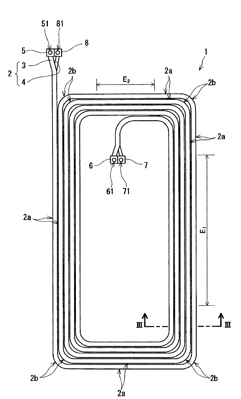
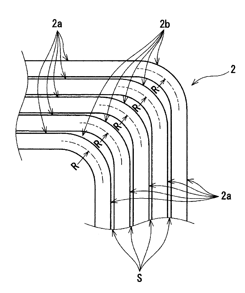
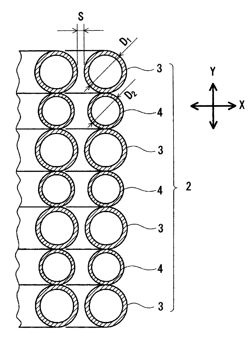
[0022] Such as Figure 1 ~ Figure 3 As shown, a heat exchanger 1 according to an embodiment of the present invention includes a spiral heat transfer tube group 2 formed in a flat rectangular plate shape. In the heat transfer tube group 2, a plurality of (four in the illustration) first heat transfer tubes 3 and a plurality of (three in the illustra...


PUM


Abstract

A heat exchanger includes a heat transfer tube group in which a plurality of first heat transfer tubes (3) through which a first fluid flows and a plurality of second heat transfer tubes (4) through which a second fluid that exchanges heat with the first fluid flows are arranged alternately while being in contact with each other. The heat transfer tube group is formed in a spiral shape by being wound in X direction perpendicular to Y direction in which the first heat transfer tubes (3) and the second heat transfer tubes (4) are arranged. A plurality of concave portions (3a) are provided on both sides, in the X direction, of an outer circumferential surface (31) of each of the first heat transfer tubes (3), along an extending direction of the first heat transfer tube (3). The plurality of concave portions (3a) form convex portions on an inner circumferential surface of the first heat transfer tube (3).

Description

technical field [0001] The present invention relates to a heat exchanger for exchanging heat between a first fluid and a second fluid, and more particularly to a heat exchanger suitable for a heat pump water heater. Background technique [0002] Conventional heat pump water heaters, air conditioners, underfloor heating devices, and the like use heat exchangers for exchanging heat between two fluids (for example, water and refrigerant, air and refrigerant). [0003] For example, it is disclosed in Patent Document 1 that Figure 10A and 10B Heat exchanger 10 is shown. In this heat exchanger 10, one round pipe 11 for water used for water supply flow and two round pipes 12 for refrigerant used for flowing refrigerant are closely connected on the entire length, and the above-mentioned round pipes 11, 12 form Wind the shape for the runway. The outer diameter of the circular tube 12 for refrigerant is set to about half of the outer diameter of the circular tube 11 for water, and...

Claims


Application Information

Patent Timeline
IPC IPC(8): F28D7/00F28F1/40F28F1/42F28D7/04
CPCF24D2200/123F28F2270/00F28F13/12F28D7/0016F28F1/426F24H4/04
Inventor 田村朋一郎小森晃
Owner PANASONIC CORP
Why Eureka
Try Eureka