Winding battery

A battery and electrode technology, applied in secondary batteries, battery electrodes, non-aqueous electrolyte battery electrodes, etc., can solve the problems of high productivity, unavailability, and difficulty in practical application, and achieve high productivity and shorten the effect of pre-doping time.

Active Publication Date: 2011-12-28
MUSASHI ENERGY SOLUTIONS CO LTD
View PDF6 Cites 21 Cited by
  • Summary
  • Abstract
  • Description
  • Claims
  • Application Information

AI Technical Summary

Problems solved by technology

[0005] In such organic electrolytic capacitors, high performance is expected, but there are problems in that it takes an extremely long time to dope lithium ions in the negative electrode in advance, and it is necessary to uniformly support lithium ions on the entire negative electrode. Large, high-capacity batteries such as cylindrical batteries with electrodes wound around them or square batteries with stacked electrodes are difficult to put into practical use
[0009] However, in such a wound storage battery, lithium metal is provided only on either one of the outer peripheral surface and the inner peripheral surface of the electrode element. Therefore, there is a problem that it takes a long time to uniformly dope the entire negative electrode with lithium ions.
Moreover, when the lithium ion supply source is provided only on the outer peripheral surface of the electrode winding unit, although high voltage and high capacity are obtained, the amount of doped lithium ions increases, so it is necessary to use a lithium ion supply source with a large thickness. The following problems: the filling amount of the electrode is reduced, and it is difficult to obtain a sufficiently high energy density
Especially in the case of manufacturing a large wound lithium ion battery, since the number of windings is increased, the time required for the doping increases to, for example, about 30 days, and therefore, its productivity is significantly reduced.
[0017] In addition, in the wound storage battery described in Patent Document 3, since the lithium ion supply source is arranged on the inner peripheral surface and the outer peripheral surface after the electrode wound unit is assembled, the manufacturing process is complicated, and thus there is a problem that it cannot be obtained. high productivity problem

Method used


Image

  • Winding battery
  • Winding battery
  • Winding battery

Examples


no. 1 approach

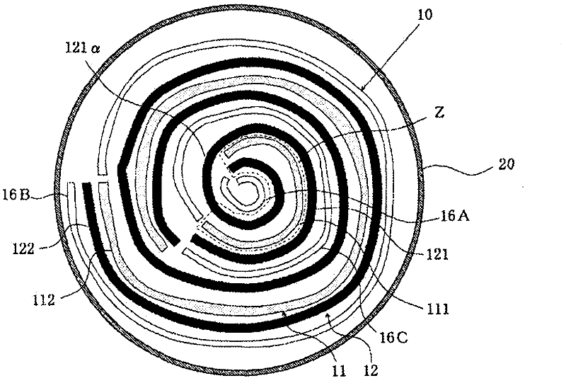
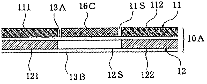
[0140] figure 1 It is an explanatory sectional view schematically showing the configuration of the wound LIC according to the first embodiment of the present invention. figure 2 is schematically shown figure 1 A cross-sectional view for explaining a state of a cross-section of an electrode laminate in a wound state of the wound electrode unit of the wound-type LIC.

[0141] The winding type LIC of this example has a cylindrical electrode winding unit 10, and the cylindrical electrode winding unit 10 is configured as follows: a strip-shaped positive electrode 11 having a positive electrode gap portion 11S and a strip-shaped positive electrode 11 having a negative electrode gap portion 12S. The negative electrode 12 is laminated with the separator interposed therebetween, specifically, the negative electrode 12, the separator 13A, and the positive electrode 11 are sequentially laminated on the separator 13B to form an electrode laminate 10A, and the electrode laminate 10A is w...

no. 2 approach

[0253] Such as Figure 16 and Figure 17 As shown, in the wound-type LIC of the second embodiment, the electrode winding unit 50 is a cylindrical member, and is configured as follows: a strip-shaped positive electrode 51 having a positive electrode gap 51S and a strip-shaped negative electrode 52 having a negative electrode gap 52S. The electrode laminate 50A is formed by laminating, specifically, the negative electrode 52 , the separator 53A, and the positive electrode 51 are sequentially laminated on the separator 53B, and the electrode laminate 50A is wound from one end thereof to form a wound electrode. The unit 50 has the same structure as that of the first embodiment except for this. In addition, in Figure 16 and Figure 17 In , the same reference numerals as those of the first embodiment denote the same components.

[0254] In wound electrode unit 50 in which positive electrode 51 , negative electrode 52 , and lithium ion supply sources 16A to 16C are laminated and w...

no. 3 approach

[0266] Figure 20 It is an explanatory cross-sectional view schematically showing the structure of a wound-type LIC according to a third embodiment of the present invention.

[0267] In this wound type LIC, an electrode wound unit 10 is provided in a packaging container 20 . Such as Figure 21 As shown, the electrode winding unit 10 sequentially stacks the negative electrode 12, the second separator 14B, and the positive electrode 11 on one side of the first separator 14A to form an electrode laminate 10A, and the electrode laminate 10A is wound in a cylindrical shape from one end thereof. The electrode winding unit 10 is formed by winding around the mandrel 19 . Here, electrode layers of the positive electrode 11 and the negative electrode 12 , which will be described later, are arranged to face each other with the second separator 14B interposed therebetween. In the illustrated example, the electrode laminate 10A is wound with the first separator 14A on the inside, whereb...


PUM

PropertyMeasurementUnit
thicknessaaaaaaaaaa
diameteraaaaaaaaaa
thicknessaaaaaaaaaa

Abstract

A wound-type accumulator which is simplified in the layout of lithium ion sources and shortened in time spent on injecting a nonprotonic organic solvent electrolytic solution and on predoping, so as to allow quick completion of assembly and obtain high productivity. The wound-type accumulator is provided with: a cylindrical wound electrode unit which has cathode and anode strips and is configured by winding from one end an electrode stack comprised of a stack of the cathode and anode with a separator disposed therebetween; and an electrolytic solution. In this wound-type accumulator, the cathode and / or anode is doped with lithium ions and / or anions by means of electrochemical contact of the cathode and / or anode with a lithium ion source. At the cathode, a cathode gap section is formed, and at least one lithium ion source is arranged at the cathode gap section or at a position opposing the cathode gap section at the anode, in a state not contacting the cathode.

Description

technical field [0001] The present invention relates to a wound storage battery having a wound electrode unit configured by stacking and winding a positive electrode and a negative electrode with a separator interposed therebetween. Background technique [0002] In recent years, negative electrodes made of carbon materials such as graphite and LiCoO 2 A battery with a positive electrode composed of a lithium metal oxide. This battery is a so-called rocking chair battery, and when the battery is charged after assembly, lithium ions are supplied from the lithium-containing metal oxide constituting the positive electrode to the negative electrode, and lithium ions are returned from the negative electrode to the positive electrode during discharge. Metal lithium is used and only lithium ions participate in charging and discharging, so it is called a lithium-ion secondary battery, which is different from a lithium battery using lithium metal. This lithium ion secondary battery ...

Claims


Application Information

Patent Timeline
Patent Type & Authority Applications(China)
IPC IPC(8): H01G9/058H01G9/016H01G9/155H01M4/70H01M10/0525H01M10/0569H01M10/0587
CPCH01G9/155H01M4/133H01M4/13H01G9/058Y02E60/122H01M10/0587H01M2/1673Y02E60/13H01M4/80H01M10/0525H01G11/06H01G11/28H01G11/82H01M50/46Y02E60/10Y02P70/50H01G11/26H01G11/50H01M4/70
Inventor 田口真渡边裕安东信雄安田直史丸茂千乡
Owner MUSASHI ENERGY SOLUTIONS CO LTD
Why Eureka
Try Eureka