
Novel technology for casting engine cylinder body by lost foam

A technology of engine cylinder block and lost foam casting, which is applied to casting molding equipment, molds, mold components, etc. It can solve the problems of waste of raw materials, high labor intensity of workers, and insufficient sand filling in the cavity, so as to save time and The effect of reducing cost, reducing cleaning workload, and reducing cost expenditure

Inactive Publication Date: 2012-01-11
CHUZHOU JINNUO INDAL
View PDF6 Cites 18 Cited by
  • Summary
  • Abstract
  • Description
  • Claims
  • Application Information

AI Technical Summary

Problems solved by technology

In terms of the molding method of this process, due to the limitation of the casting direction, the cavity inside the body cannot be filled with sand, or the sand cannot be added, so that the method of adding sand cores is used, which causes a waste of raw materials. After the castings are out of the box, the sand sticks seriously, resulting in a large amount of cleaning work in the later stage and high labor intensity for the workers
In terms of pouring methods, top pouring or side pouring is used. These two pouring methods are prone to a series of defects such as slag curling, slag pores, insufficient pouring, and box collapse, which will cause the cylinder to be scrapped due to casting defects.

Method used


Image

  • Novel technology for casting engine cylinder body by lost foam
  • Novel technology for casting engine cylinder body by lost foam
  • Novel technology for casting engine cylinder body by lost foam

Examples


Embodiment 1

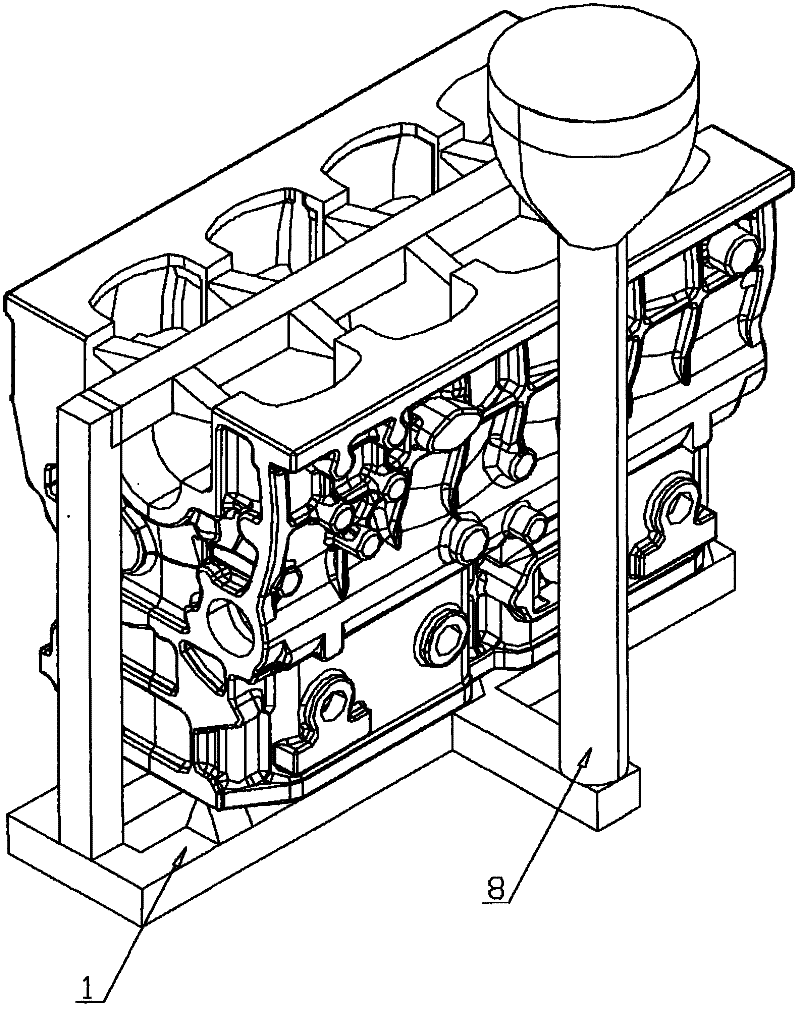
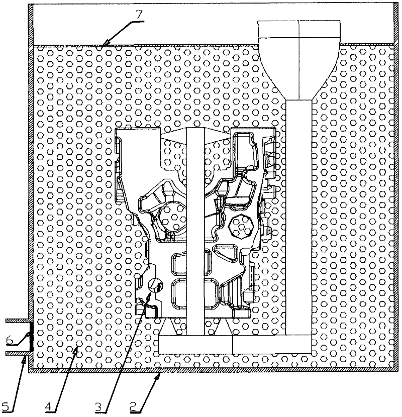
[0021] like figure 1 , figure 2 As shown, a new process of using lost foam casting engine block, the specific steps are as follows:

[0022] ① According to the drawings and casting requirements, after using 3D software to carry out three-dimensional modeling of the cylinder to be cast, according to the shape characteristics of the cylinder to be cast and the requirements of the casting process, the three-dimensional modeling is cut into several dies and the molds for each die are manufactured ;

[0023] ②Inject expandable foam beads into the mold manufactured in step ①, and obtain the lost foam mold of the cylinder body after heating and cooling. drying in the drying room;

[0024] ③The lost foam mold pieces dried in step ② are bonded as a whole as required, and the casting system is bonded on the bottom, that is, the lost foam model 1 of the cylinder body is obtained;

[0025] ④ Dip 1 to 3 layers of special paint on the surface of the lost foam model 1, so that the thick...


PUM


Abstract

The invention discloses a novel technology for casting an engine cylinder body by lost foam, and relates to the field of casting technologies. The novel technology is characterized by comprising the following steps of carrying out three-dimensional modeling by three-dimensional software, slitting the three-dimensional model obtained by the previous step into multiple model sheets, preparing molds for preparation of the model sheets, pouring expandable foam beads into the molds, carrying out heating and cooling processes to obtain lost foam model sheets of the engine cylinder body, drying the lost foam model sheets, bonding the dried lost foam model sheets into an integral body according to requirements, bonding a casting system on the bottom of the integral body to obtain a lost foam model, carrying out dip-coating treatment on the surface of the lost foam model by specialized paint 1 to 3 times, putting the lost foam model coated with the specialized paint into a drying room to carry out drying treatment, putting the dried lost foam model into a three-dimensional vibration sand box, adding gradually dry sand into the three-dimensional vibration sand box, covering a film on the surface of the three-dimensional vibration sand box to sealing the three-dimensional vibration sand box, pouring melt obtained by a smelting process into the casting system so that the lost foam model is melted and the melt occupies a space occupied originally by the lost foam model, and cooling the melt to solidification to obtain an engine cylinder body casting. The novel technology improves a qualified rate, saves resources and reduces a cost for enterprises.

Description

technical field [0001] The invention relates to the field of casting technology, in particular to a novel technique for casting an engine cylinder block with lost foam. Background technique [0002] Now the lost foam casting engine block is roughly divided into the following steps. First, use the lost foam mold to manufacture each die of the engine body, and then bond each die into a whole to make it a lost foam model of the cylinder. Then put the model into the sand box, add sand and vibrate it, and then cast it. In terms of the molding method of this process, due to the limitation of the casting direction, the cavity inside the body cannot be filled with sand, or the sand cannot be added, so that the method of adding sand cores is used, which causes a waste of raw materials. After the castings are out of the box, the sand sticks seriously, resulting in a large workload for later cleaning and high labor intensity for workers. In terms of pouring methods, top pouring or si...

Claims


Application Information

Patent Timeline
Patent Type & Authority Applications(China)
IPC IPC(8): B22C7/00B22C9/02
Inventor 马正松张玉胜钱俊
Owner CHUZHOU JINNUO INDAL
Learn More