Separated thermal cycle sludge dry method and device thereof

A technology of sludge drying and thermal circulation, which is applied in the direction of sludge treatment through temperature control, dehydration/drying/concentrated sludge treatment, etc. problems, to achieve the effect of reducing energy consumption and improving thermal cycle efficiency

Inactive Publication Date: 2012-01-11
郭少仪 +1
View PDF6 Cites 19 Cited by
  • Summary
  • Abstract
  • Description
  • Claims
  • Application Information

AI Technical Summary

Problems solved by technology

During the drying process, the generated steam contains a large amount of non-condensable gas, and brings out a lot of dirt that adheres to the inner wall of the pipeline and equipment, and is corrosive to a certain extent, which seriously affects the operation of the steam compressor
In addition, there is a high bonding area in the sludge drying process, which brings great difficulties to the design, manufacture and operation of drying equipment
In addition, its thermal conductivity is poor, and the heat transfer effect is not good.

Method used


Image

  • Separated thermal cycle sludge dry method and device thereof
  • Separated thermal cycle sludge dry method and device thereof
  • Separated thermal cycle sludge dry method and device thereof

Examples


Embodiment 1

[0045] Embodiment 1: a kind of isolated thermal cycle sludge drying method, the processing steps of this method are:

[0046] (1) Inject the wet sludge into the drying device for drying;

[0047] (2) The steam and non-condensable gas produced by drying the wet sludge in the drying device are pumped to the heat exchanger through the fan, and exchange heat with the working medium water with a lower temperature outside the heat exchanger tubes;

[0048] (3) The steam is condensed into water droplets in the heat exchanger and enters the wet material preheating conveyor through the water vapor separation device with the non-condensable gas. The water condensed by the steam preheats the wet sludge injected into the wet material preheating conveyor. Hot, non-condensable gas enters the heat exchange combustion furnace through the gas outlet of the water vapor separation device to be burned, and the heat generated by the combustion of the non-condensable gas is transported to the heat ...

Embodiment 2

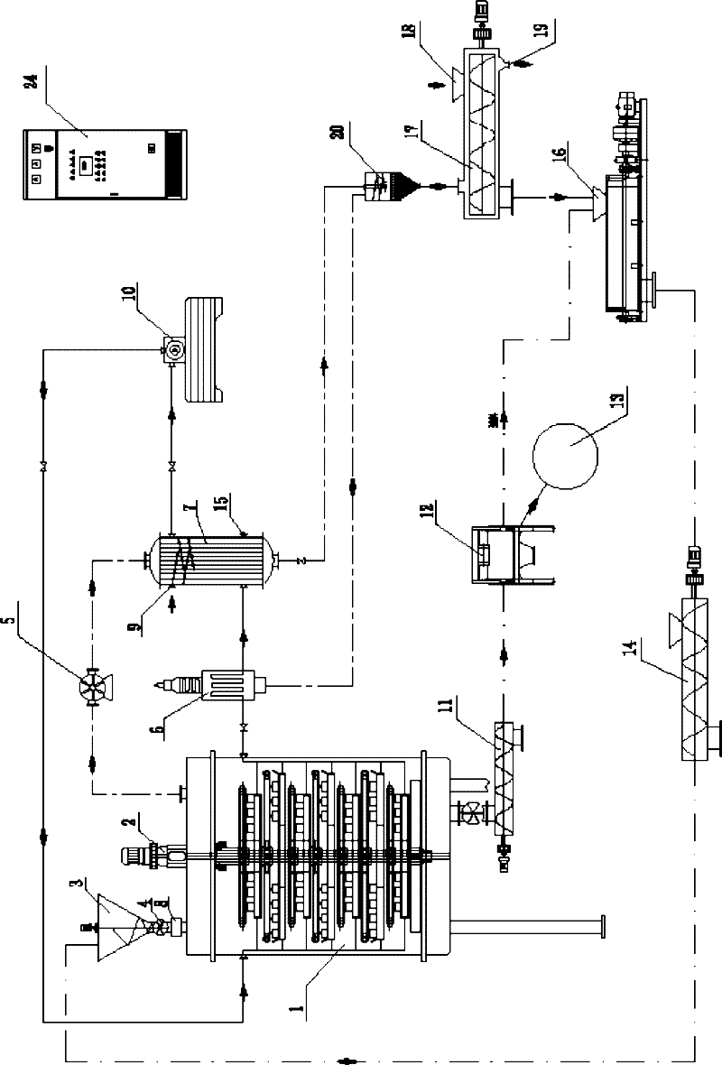
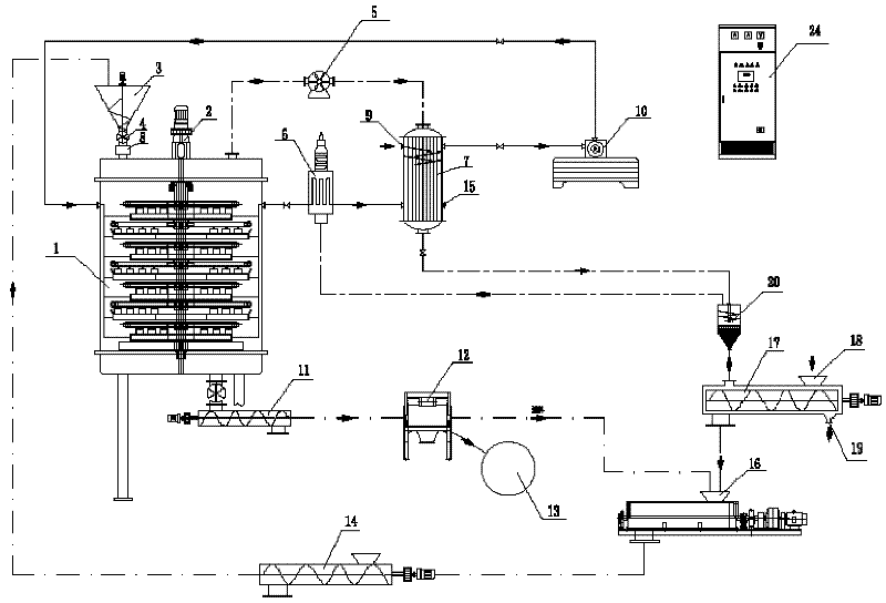
[0052] Embodiment 2: as figure 1 As shown, an isolated thermal cycle sludge drying device includes a disc-type continuous drying tank 1 driven by a frequency conversion speed regulating motor 2 to rotate the tray, a heat exchange combustion furnace 6, a heat exchange evaporator 7, a vapor compression machine 10, wet material preheating conveyor 17, water vapor separation device 20, material mixing mixer 16, screening proportioner 12, screw conveyor, the bottom outlet of quantitative feeder 3 passes through the first continuous locker 4 on the same plate The top of the disc-type continuous drying tank 1 is connected to the feed inlet of the electromagnetic valve 8; the steam outlet of the disc-type continuous drying tank 1 is connected to the steam inlet of the heat-exchanging tube in the inner cavity of the heat-exchanging evaporator 7 through the induced draft fan 5, The condensed water outlet of the heat-exchanged evaporator 7 is connected to the condensed water inlet at one...

Embodiment 3

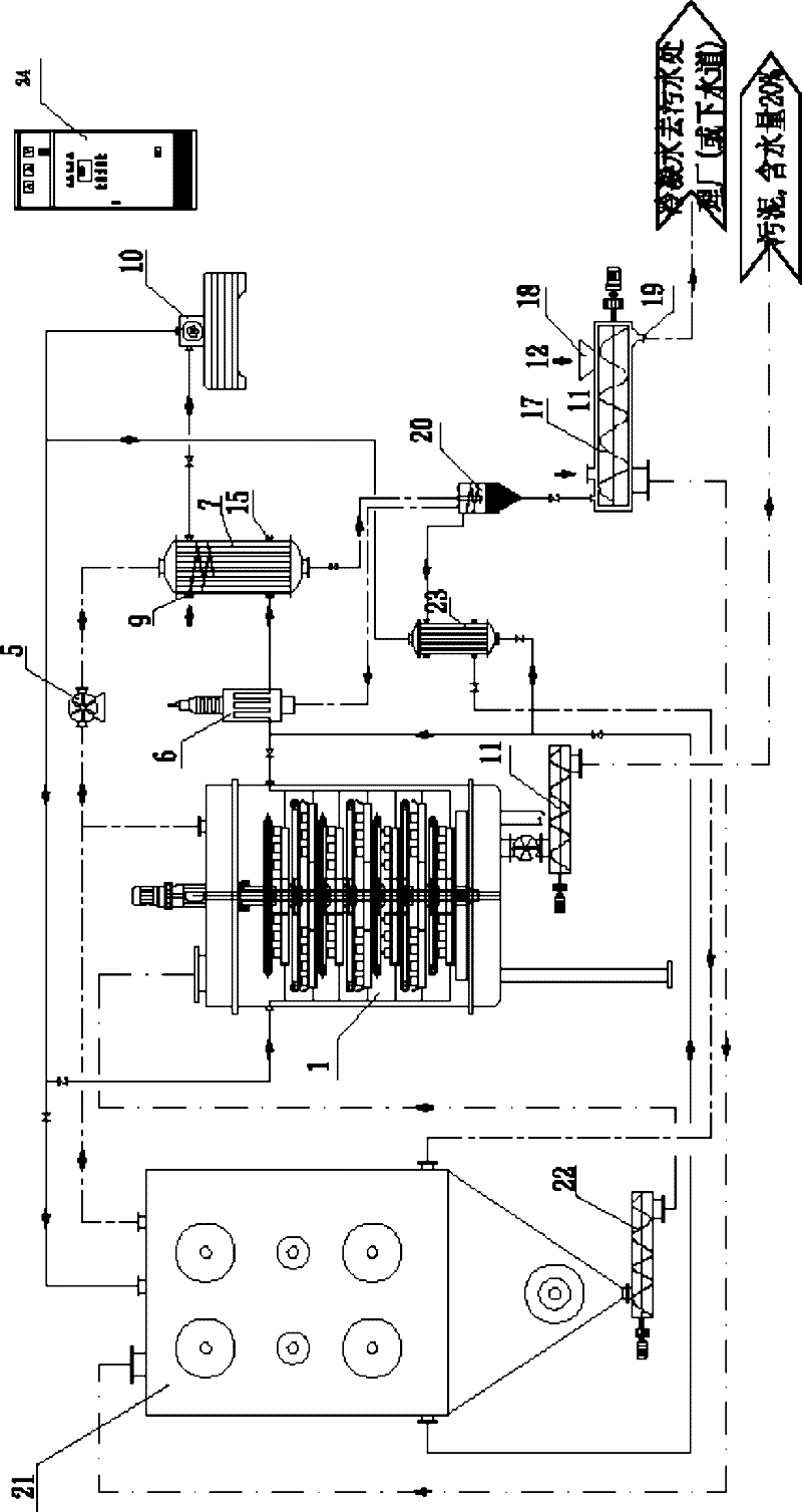
[0065] Embodiment 3: as figure 2As shown, an isolated thermal cycle sludge drying device includes a soft granulation drying machine 21, a disc-type continuous drying tank 1 driven by a frequency conversion speed regulating motor 2 to rotate the tray, a heat exchange combustion furnace 6, and a heat transfer furnace 6. Thermal evaporator 7, steam compressor 10, air preheating device 23, wet material preheating conveyor 17, water vapor separation device 20, screening proportioner 12, screw conveyor; : steam from soft granulation drying machine 21 The outlet and the steam outlet of the disc-type continuous drying tank 1 are respectively connected to the steam inlet of the heat exchange tube in the inner cavity of the heat exchange evaporator 7 through the induced draft fan 5, and the condensed water outlet of the heat exchange evaporator 7 heat exchange tube is passed through The water vapor separation device is connected with the condensed water inlet at one end of the outer pe...


PUM


Abstract

The invention relates to a treatment technique of sludge produced by sewage treatment, in particular to a separated thermal cycle sludge dry method and a device thereof. The method comprises the following steps: putting wet sludge in a drying tank for drying, leading out the steam produced by drying through a fan, letting the steam enter an evaporator be condensed into water, letting the peripheral water of tubes as working fluid be subject to evaporation to generate secondary steam, compressing the secondary steam by a vapor compressor to heat, then putting the secondary steam processed by heating as an outer heating source of the drying tank in a heat transfer of the drying tank; supplying heat to sludge indirectly, letting the steam after the heat supply be condensed into water, letting the water enter the evaporator through the heat absorption of the tubes of the combustion furnace to form a closed cycle of the working fluid. According to the invention, evaporation latent heat of water and heat value of non-condensable gas are fully recycled, to that the energy consumption is minimized; and because of the isolation effect of the evaporator, the vapor compressor is separated from the products formed by anhydration of the sludge, so that the system can stably run in long-term, and the investment cost is greatly reduced.

Description

technical field [0001] The invention relates to a technology for treating sludge produced by sewage treatment, and further refers to an isolated thermal cycle sludge drying method and device. Background technique [0002] my country's 863 plan resources and environment technology field "key technology and equipment for safe disposal of sludge in urban sewage treatment plants" key project application guide clearly stated that with the popularization and operation of urban sewage treatment plants in my country, sludge in urban sewage treatment plants With the rapid increase in output, how to solve the way out of sludge disposal has become a major environmental problem to be solved urgently in the process of urban development in my country. Research and development of key technologies and equipment for sludge treatment in urban sewage treatment plants that are suitable for my country's national conditions and have independent intellectual property rights is an urgent need for my...

Claims


Application Information

Patent Timeline
Patent Type & Authority Applications(China)
IPC IPC(8): C02F11/12C02F11/18
Inventor 郭少仪戴田华邢升阳房艳霞郑八满
Owner 郭少仪
Why Eureka
Try Eureka