Fixing device and method for refractory material in strip steel heat treatment furnace

A technology for heat treatment furnaces and refractories, which is applied in heat treatment furnaces, heat treatment equipment, furnaces, etc., can solve the problems of a large number of anchoring nails, a large number of welding materials and welding labor, a lot of labor and time, and save labor costs. , The effect of saving labor costs and saving welding materials

Inactive Publication Date: 2012-01-11
WISDRI WUHAN WIS IND FURNACE
View PDF5 Cites 8 Cited by
  • Summary
  • Abstract
  • Description
  • Claims
  • Application Information

AI Technical Summary

Problems solved by technology

[0008] 1. High cost: For the entire heat treatment furnace, the anchor nails are densely distributed and the number is huge, requiring a lot of welding materials and welding labor
[0009] 2. Poor welding quality: Generally, the anchor nails are directly welded to the furnace shell on site by a special welding torch
This form of welding is not firm, and a large number of anchor nails often fall off during the welding process.
[0010] 3. Low work efficiency: It takes a lot of manpower and time to weld and handle anchor nails with poor welding quality on site
[0011] 4. High energy consumption: due to the large number of anchor nails in the annealing furnace, it is easy to form a large "thermal bridge" and cause a large heat loss

Method used


Image

  • Fixing device and method for refractory material in strip steel heat treatment furnace
  • Fixing device and method for refractory material in strip steel heat treatment furnace
  • Fixing device and method for refractory material in strip steel heat treatment furnace

Examples


Embodiment Construction

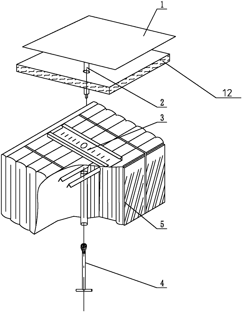
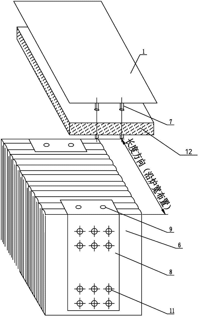
[0035] The present invention selects the refractory ceramic fiber folding block 6 to replace the current refractory ceramic fiber module 5 for the side wall and top of the heat treatment furnace. The only difference between the refractory ceramic fiber folded block and the fiber module is that there is no hanging structure inside the former. Therefore, the refractory ceramic fiber folded block is generally used in the bottom of the furnace.

[0036] refer to Figure 2-5 , the refractory ceramic fiber folding block provided by the present invention and its fixing method are as follows:

[0037] The first step is to draw a line according to the requirements of the refractory design drawing, and specify the welding position of the supporting bolt 7;

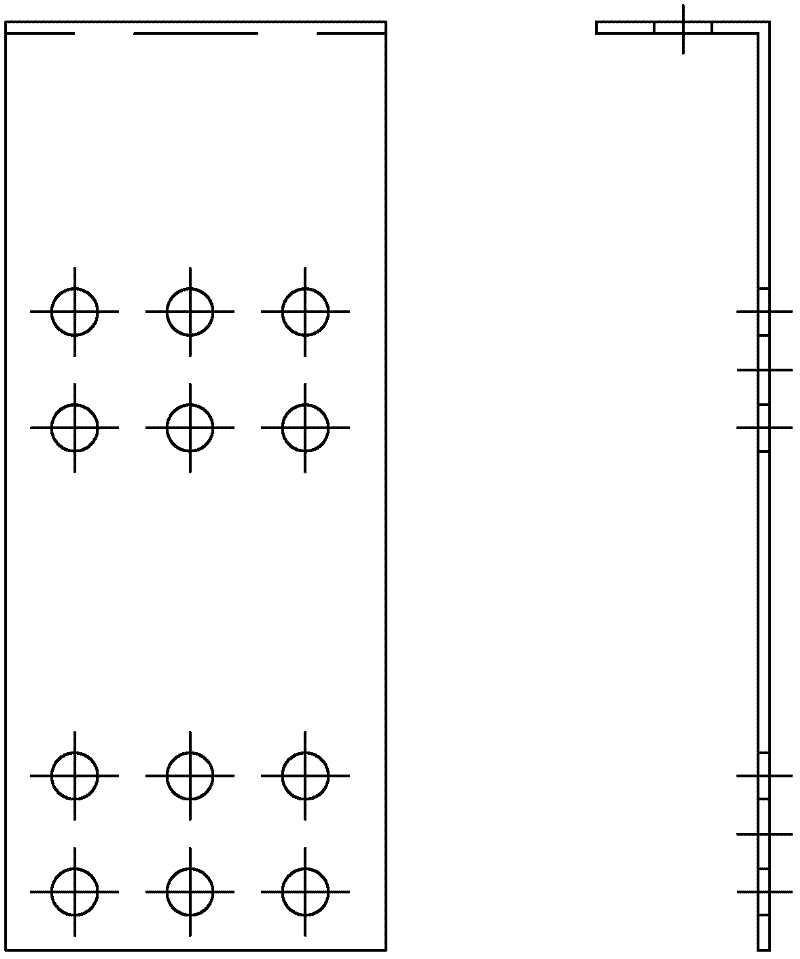
[0038] In the second step, the supporting bolts are welded on the steel plate of the furnace shell, and then the L-shaped steel plate 8 is inserted into the bolts through the positioning holes 9 (the number of positioning holes in ...


PUM


Abstract

The invention provides a fixing device and method for a refractory material in a strip steel heat treatment furnace. The fixing device comprises a furnace shell steel plate, a thermal insulation layer and fireproof ceramic fiber folding blocks, and the furnace shell steel plate, the thermal insulation layer and the fireproof ceramic fiber folding blocks are connected in order. The fixing method comprises the following steps: marking a line to specify welding positions of bolts; welding bolts on the furnace shell steel plate and allowing the bolts to pass through the thermal insulation layer; sleeving an L-shape steel plate onto the bolts through location holes in the L-shape steel plate and fixing nuts on the bolts; destroying screw threads below the nuts by spot welding after the nuts are positioned; allowing penetration ribs to pass through suspension apertures in the L-shape steel plate; sequentially sleeving the fireproof ceramic fiber folding blocks on the penetration ribs and installing the fireproof ceramic fiber folding blocks in place; repeating the previous step so as to install all the rest fireproof ceramic fiber folding blocks until the furnace is filled with the fireproof ceramic fiber folding blocks. According to the invention, the rest fireproof ceramic fiber folding blocks are fixed on a furnace wall or a furnace roof; meanwhile, problems resulting from utilization of fireproof ceramic fiber modules are avoided successfully.

Description

technical field [0001] The invention relates to the field of fixing refractory materials, in particular to an energy-saving setting and fixing method for refractory ceramic fibers in a heat treatment furnace for cold-rolled strip steel. Background technique [0002] Due to the advantages of excellent chemical stability, excellent thermal stability, low thermal conductivity, low heat capacity and diversified forms, refractory ceramic fibers are widely used in the field of cold-rolled strip heat treatment furnaces. Refractory ceramic fiber modules have the following advantages and are widely used in furnace insulation. 1. It is in a pre-compressed state before installation. After the installation is in place, the stitches can be removed to expand, and its expansion can compensate for fiber shrinkage and improve the heat insulation performance of the fiber furnace lining; It is not easy to fall off; 3. It can be designed and manufactured according to the installation space str...

Claims


Application Information

Patent Timeline
Patent Type & Authority Applications(China)
IPC IPC(8): C21D9/54
Inventor 武斌徐少春易敏
Owner WISDRI WUHAN WIS IND FURNACE
Why Eureka
Try Eureka