Light emitting diode (LED) lamp lens

An LED lamp lens and lens technology, which is applied to lighting devices, light sources, components of lighting devices, etc., can solve the problems of light glare, high concentration, and light glare of LED light sources, so as to reduce the price of lamps, uniform light distribution, and save materials. cost effect

An LED lamp lens and lens technology, which is applied to lighting devices, light sources, components of lighting devices, etc., can solve the problems of light glare, high concentration, and light glare of LED light sources, so as to reduce the price of lamps, uniform light distribution, and save materials. cost effect

CN102313245BInactive Publication Date: 2013-07-31中国科学院宁波材料技术与工程研究所湖州新能源产业创新中心

Image

  • Light emitting diode (LED) lamp lens
  • Light emitting diode (LED) lamp lens
  • Light emitting diode (LED) lamp lens

Examples


Embodiment Construction

[0043] The present invention will be further described below in conjunction with the accompanying drawings.

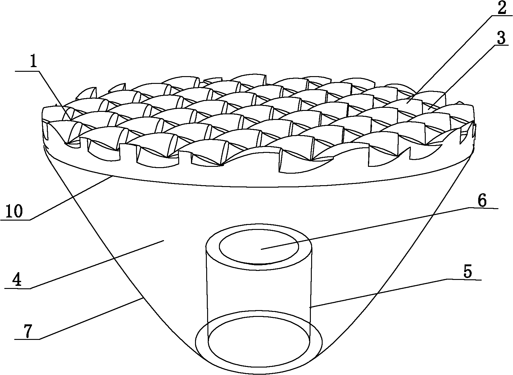
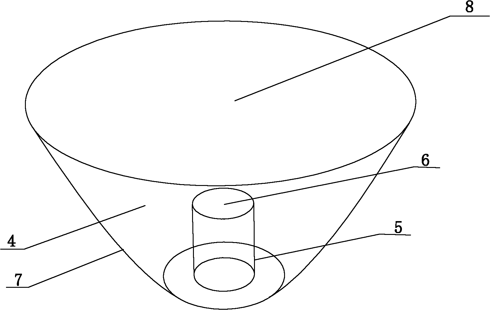
[0044] like figure 1 , figure 2 Shown, be the LED lamp lens of the present invention, comprise the collimating lens 4 of conical frustum shape or approximately frustum of conical shape; The collimating lens 4 is provided with a refraction groove 5 on one end surface opposite to the light-emitting surface 8 of the collimating lens 4;

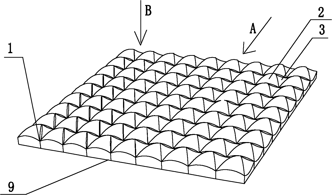
[0045] like image 3 , Figure 4 , Figure 5 As shown, the incident surface 9 of the thin-plate lens 1 is a smooth plane, and the light-emitting surface of the thin-plate lens 1 is composed of the convex surfaces of several triangular convex microlenses 2 of the same size and the concave surfaces of several triangular concave concave microlenses 3 of the same size; The convex surface of the triangular convex microlens 2 and the concave surface of the triangular concave microlens 3 face away from the light emitting surface 8 of the c...


PUM


Abstract

The invention discloses a light emitting diode (LED) lamp lens, which comprises a collimation lens, wherein the side face of the collimation lens is a total reflection face; a light outlet face of a sheet lens consists of convex faces of triangular convex lenses and concave faces of triangular concave lenses; and the collimation lens is provided with a refraction groove at an end plane opposite to the light outlet face of the collimation lens. Through the combination of the collimation lens and the sheet lens, the LED lamp lens is applicable to different LED chips and is more universal; and light which is emitted by the LED lamp lens is distributed uniformly and softer.

Description

technical field [0001] The invention relates to the field of LED lighting equipment, in particular to an LED lamp lens. Background technique [0002] A light-emitting diode (Light-Emitting-Diode, referred to as LED) is a semiconductor that can convert electrical energy into light energy, and its core component is an LED chip. [0003] As a high-profile new-generation light source, LED has many advantages such as small size, large luminous flux, all-solid-state operation, compact structure, green and pollution-free, high efficiency, and energy saving. However, because its typical light output characteristic is a half-space Lambertian light source, direct application is likely to cause shortcomings such as unreasonable brightness distribution and glare. Therefore, secondary light distribution technology is usually used in lighting applications to redistribute light. Various LED optical lenses have become the most Ideal secondary light distribution technology. [0004] At pre...

Claims


Application Information

Patent Timeline
31 Jul 2013
Publication
CN102313245B
IPC
F21V5/04; F21Y101/02
Inventors
张贤鹏; 吴秋萍