Input/output structure of broadband phase shift travelling wave tube

An input-output, traveling wave tube technology, applied in the field of vacuum electronics, can solve the problems of inability to conduct experimental research on sinusoidal waveguide slow-wave systems, wide working bandwidth of slow-wave structures, and no input and output structures, etc., achieving easy processing and realization, simple structure , Improve the effect of working current

Inactive Publication Date: 2012-01-11
UNIV OF ELECTRONICS SCI & TECH OF CHINA
View PDF5 Cites 16 Cited by
  • Summary
  • Abstract
  • Description
  • Claims
  • Application Information

AI Technical Summary

Problems solved by technology

Experimental studies of sinusoidal waveguide slow wave systems are not possible due to lack of suitable input and output structures
The design difficulties of this input-output structure are: 1. The cross-section of the slow-wave structure of the phase-shifted traveling wave tube is rectangular, and the band-shaped electron beam and the slow electromagnetic wave share a channel; 2. The working bandwidth of the slow-wave structure is very wide. None of the coupling devices can meet its bandwidth requirements

Method used


Image

  • Input/output structure of broadband phase shift travelling wave tube
  • Input/output structure of broadband phase shift travelling wave tube
  • Input/output structure of broadband phase shift travelling wave tube

Examples


Embodiment Construction

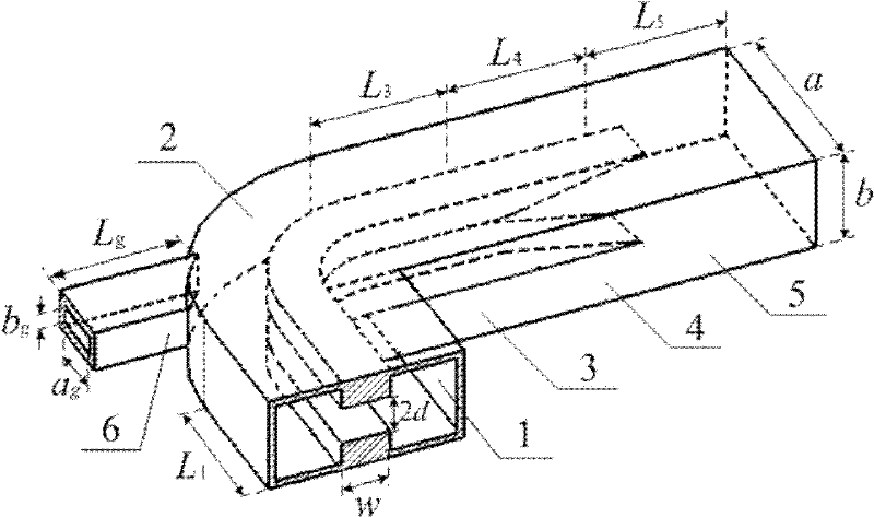
[0022] An input-output structure of a broadband phase-shifting TWT, such as figure 2 As shown, there are six waveguide components: the first double-ridge loaded rectangular waveguide 1, the 90-degree bent double-ridge-loaded rectangular waveguide 2, the second double-ridge-loaded rectangular waveguide 3, and the double-ridge-loaded rectangular waveguide 4 with double-ridge gradient , the first rectangular waveguide 5 and the second rectangular waveguide 6;

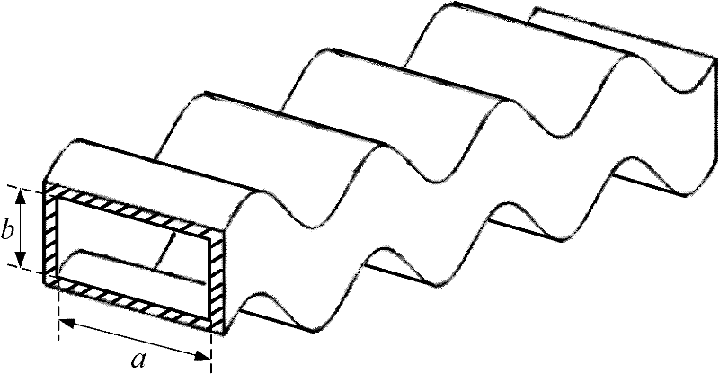
[0023] The width dimensions of the first double-ridge loaded rectangular waveguide 1, the 90-degree curved double-ridge-loaded rectangular waveguide 2, the second double-ridge-loaded rectangular waveguide 3, the double-ridge-loaded rectangular waveguide 4 with double-ridge gradient, and the first rectangular waveguide 5 Consistent with the narrow side size, marked as wide side size a, narrow side size b; the first double ridge loaded rectangular waveguide 1, the second double ridge loaded rectangular waveguide 3, the doub...


PUM


Abstract

The invention, which belongs to the vacuum electronic technology field, relates to an input / output structure of a broadband phase shift travelling wave tube. The structure comprises six parts of waveguide type elements: a first double-ridge loading rectangular wave guide; a double-ridge loading rectangular wave guide, which is in a bending state of 90 degrees; a second double-ridge loading rectangular wave guide; a double-ridge gradient double-ridge loading rectangular wave guide; a first rectangular wave guide and a second rectangular wave guide. The first double-ridge loading rectangular wave guide and the second double-ridge loading rectangular wave guide are respectively connected with two ends of the double-ridge loading rectangular wave guide that is in a 90 degree bending; the double-ridge gradient double-ridge loading rectangular wave guide is connected between the second double-ridge loading rectangular wave guide and the first rectangular wave guide; and the second rectangular wave guide is connected with an outboard curved surface window of the double-ridge loading rectangular wave guide that is in a 90 degree bending, wherein a central axis of the double-ridge loading rectangular wave guide that is in a 90 degree bending is superposed with a central axis of the first rectangular wave guide. According to the invention, broadband microwave signal energy and a band shape electronic beam can be well introduced and a sine wave guide structure can be lead out; besides, the input / output structure is simple and is easy to process and realize.

Description

technical field [0001] The invention belongs to the technical field of vacuum electronics, and in particular relates to an input-output structure of a terahertz phase-shifting traveling wave tube. Background technique [0002] The development and application of the electromagnetic spectrum in the terahertz band is the trend of science and technology development, and the broadband terahertz power source is the key technology. Traveling wave tubes have the characteristics of high power, high efficiency, high gain, wide frequency band and long life, and have great potential in realizing broadband high-power terahertz sources. However, in the terahertz band above 100 GHz, traditional traveling wave tubes cannot meet the requirements of broadband high-power terahertz sources due to large high-frequency loss and strong reflection. The working principle of the phase-shifted traveling wave tube was first published by an American scholar in 2008, and pointed out that it can realize ...

Claims


Application Information

Patent Timeline
Patent Type & Authority Applications(China)
IPC IPC(8): H01J23/36
Inventor 魏彦玉许雄赖剑强宫玉彬黄民智王文祥
Owner UNIV OF ELECTRONICS SCI & TECH OF CHINA
Why Eureka
Try Eureka