

Giant magnetoresistive effect current sensor using amorphous alloy magnetic ring structure
A current sensor, amorphous alloy technology, applied in the measurement of current/voltage, instrument, measurement of electrical variables and other directions, can solve the problems of high insulation requirements, difficult installation, bulky and other problems, to achieve wide frequency response, good stability, Sensitive effect
- Summary
- Abstract
- Description
- Claims
- Application Information
AI Technical Summary
Problems solved by technology
Method used
Image

Examples
Embodiment Construction
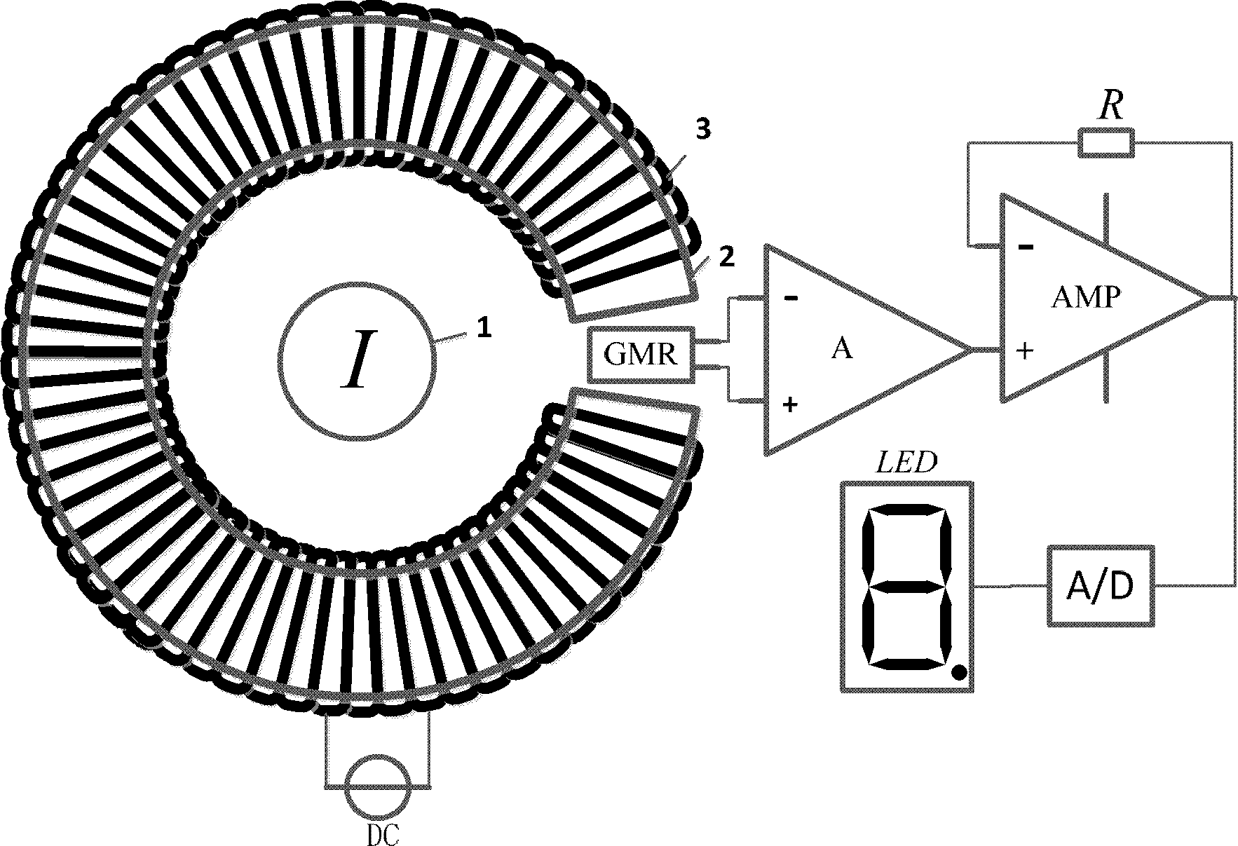
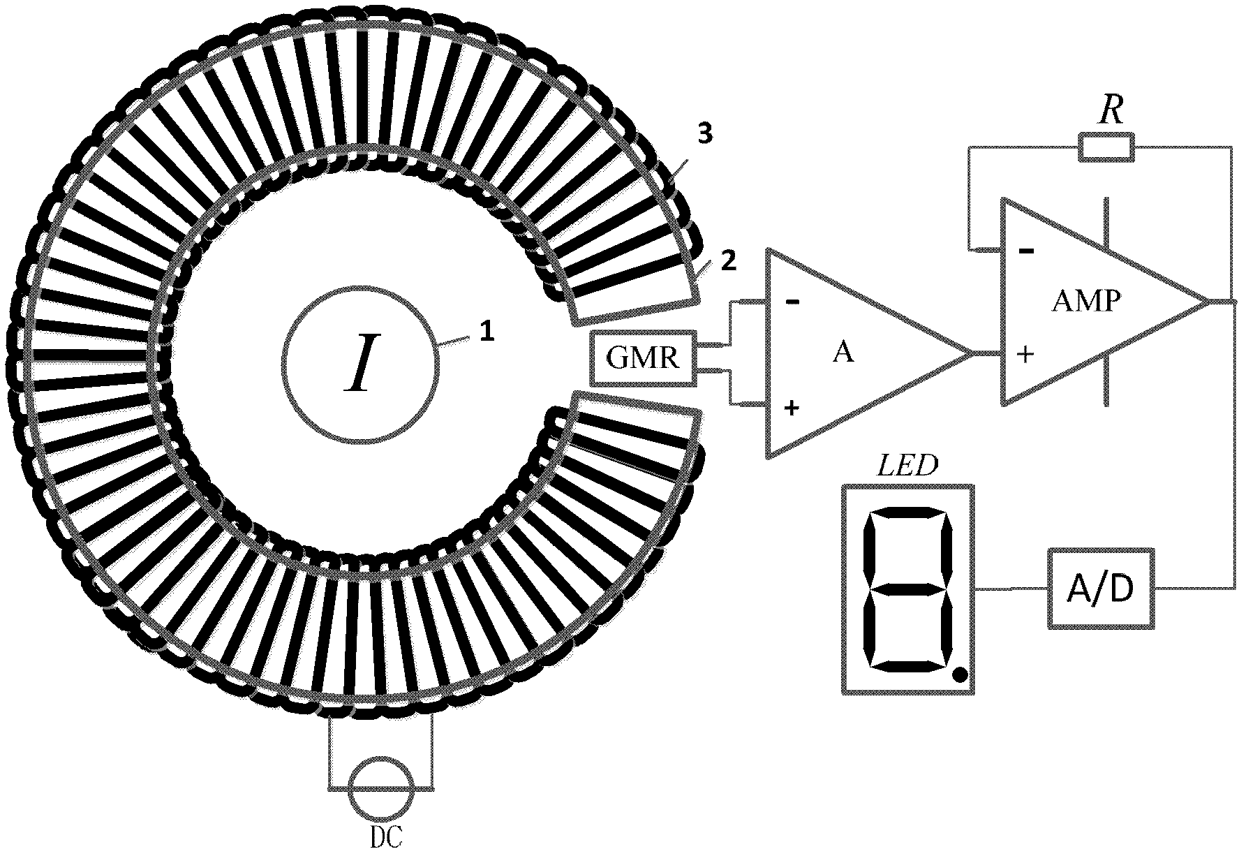
[0013] The giant magnetoresistance effect current sensor that adopts amorphous alloy magnetic ring structure that the present invention proposes, its structure is as follows figure 1 As shown, it includes amorphous alloy magnetic ring 2, DC constant current source DC, DC bias coil 3, multilayer film giant magnetoresistance effect chip GMR, instrumentation amplifier A, operational amplifier AMP, voltage following resistor R, and analog-to-digital converter A / D and Nixie tube display LED. The DC bias coil is wound on the amorphous alloy magnetic ring, and the DC constant current source supplies power to the DC bias coil; the measured wire 1 passes through the amorphous alloy magnetic ring 2, and the amorphous alloy magnetic ring 2 has an air gap . The multilayer film giant magnetoresistance effect chip GMR is placed in the air gap of the amorphous alloy magnetic ring. The positive output terminal and the negative output terminal of the multilayer film giant magnetoresistance e...
PUM
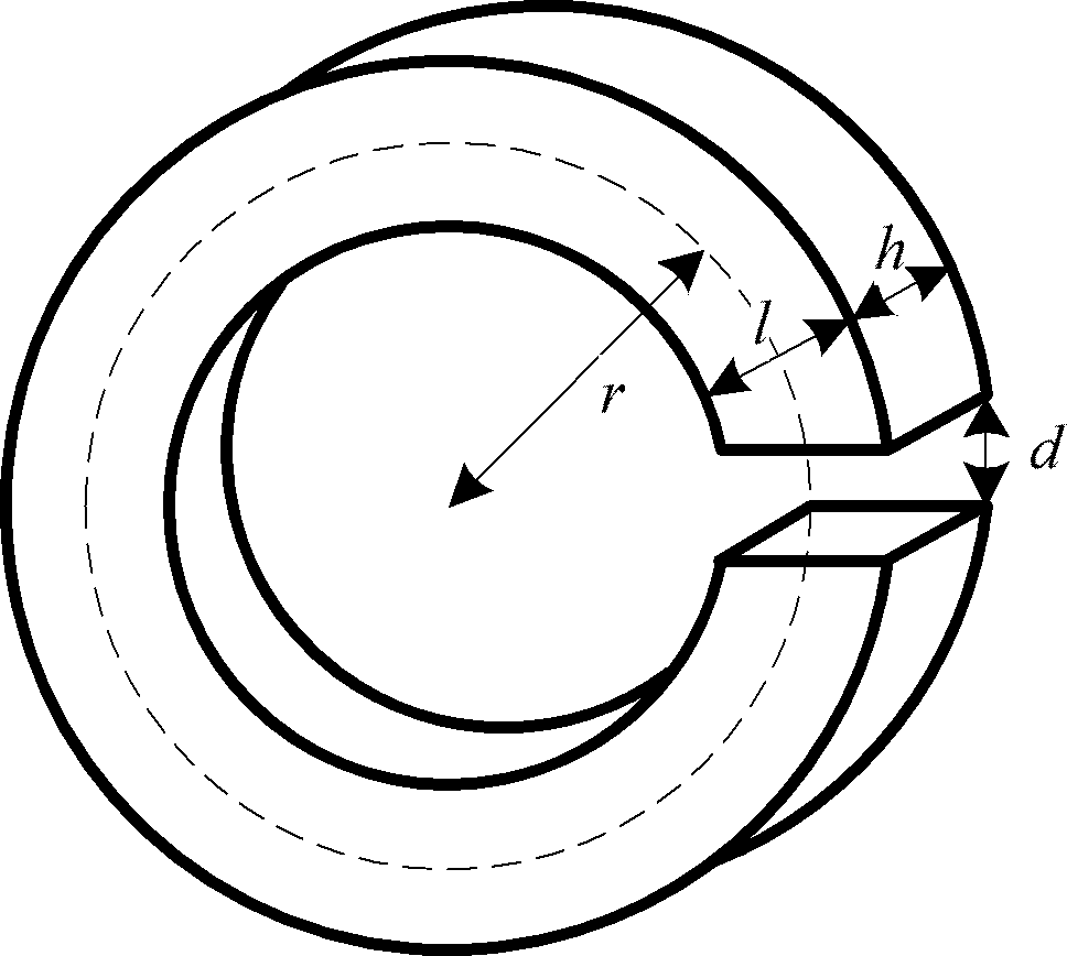
| Property | Measurement | Unit |
|---|---|---|
| radius | aaaaa | aaaaa |
| thickness | aaaaa | aaaaa |
| width | aaaaa | aaaaa |
Abstract
Description
Claims
Application Information