
Height measurement method for continuous wave search radar

A technology for searching radars and beams, which is applied in the altimetry field of small-scale air search and target indication radars. effect of difficulty

Inactive Publication Date: 2012-01-18
TIANWEI ELECTRONICS SYST ENG
View PDF2 Cites 9 Cited by
  • Summary
  • Abstract
  • Description
  • Claims
  • Application Information

AI Technical Summary

Problems solved by technology

[0002] The current three-coordinate search radar basically adopts the working mode of the pulse system, especially the widely popular phase-scan antenna search radar, because it uses time separation to alternately work in different elevation beams, so it is not suitable for the continuous wave working system, so in It is difficult to achieve three coordinates in continuous wave radar

Method used


Image

  • Height measurement method for continuous wave search radar
  • Height measurement method for continuous wave search radar
  • Height measurement method for continuous wave search radar

Examples


Embodiment Construction

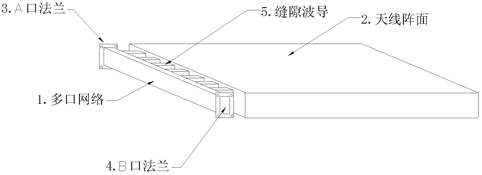
[0040] see figure 1 , the present invention utilizes the principle of ratio-amplitude altimetry to generate a pair of mirror-image distribution beams in the elevation plane of the receiving antenna array. The upper and lower beams have a certain separation angle, and the two beams intersect at the 3dB point. The beams are generated by the receiving array of the same aperture, and the aperture utilization rate is high.

[0041] figure 1 It is a receiving antenna array with two image beams, and its feed network is connected to the waveguide array by using a multi-port network 1 (a multi-channel power distribution network) to reduce power loss and simplify the structure of the feed network. The echoes received by the slot waveguide 5 of the antenna front 2 are sent to the input ends of two symmetrical microwave receivers A and B through the multi-port network 1, and the slot waveguide 5 of the antenna front is determined by the width of the pitch beam. The multi-port network 1 ...


PUM


Abstract

The invention discloses a height measurement method for a continuous wave search radar. In the method, a multi-port network is adopted to receive a pair of wave beams in mirror image distribution generated by a pitching surface of an antenna array; a slot waveguide and two output ports are distributed on the multi-port network; the two output ports of the multi-port network are connected to input ends of two paths of symmetric microwave receivers respectively; the used microwave receivers are superheterodyne receivers; the two paths of microwave receivers change the received echo to be intermediate frequency through amplification, frequency mixing and filtration and generate I and Q-baseband signals through amplification of an amplification filter and orthogonal demodulation; the I and Q-baseband signals are converted into digital quantity through A / D (Analog to Digital) conversion; modulo operation is performed through a signal processing module; a directional value is solved by using a sum-difference device; and a numerical value of an elevation angle is obtained from a pulse-out meter or through polynomial fitting by taking the directional value as an address. The method is easy to implement, has high data rate and is suitable for a small-sized three-coordinate search radar.

Description

technical field [0001] The invention belongs to the altimetry technology of small air-to-air search and target indication radar, and relates to an altimetry method of continuous wave search radar. Continuous wave three-coordinate search radar. Background technique [0002] The current three-coordinate search radar basically adopts the working mode of the pulse system, especially the widely popular phase-scan antenna search radar, because it uses time separation to alternately work in different elevation beams, so it is not suitable for the continuous wave working system, so in It is difficult to realize three coordinates in continuous wave radar. However, the advantages of continuous wave radar equipment, such as simple equipment, high receiving sensitivity, low transmission power, and a certain low probability of interception, have attracted many designers, so that radar designers continue to explore the technology of three-coordinate altimetry in the continuous wave syste...

Claims


Application Information

Patent Timeline
IPC IPC(8): G01S13/32
Inventor 徐正平
Owner TIANWEI ELECTRONICS SYST ENG
Learn More