Pole piece for laminated lithium ion battery and laminated lithium ion battery
A lithium-ion battery and lamination technology, which is applied in the direction of secondary batteries, battery components, circuits, etc., can solve the problems of unfavorable continuous discharge of large current, uneven heat dissipation, and easy inflation of the battery, so as to improve heat generation, Effect of increasing area and reducing internal resistance
- Summary
- Abstract
- Description
- Claims
- Application Information
AI Technical Summary
Problems solved by technology
Method used
Image

Examples
Embodiment 1
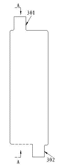
[0065] image 3 A schematic diagram of the front view structure of a pole piece for a laminated lithium-ion battery provided in this embodiment;
[0066] Figure 4 for image 3 Schematic diagram of the A-A cross-sectional structure.
[0067] see image 3 , 4 As shown, a pole piece for a laminated lithium-ion battery provided in this embodiment is composed of a current collector foil and an electrode material layer 402 coated on the surface of the current collector foil 401 . Its specific structure is as follows:
[0068] On the first width end side of the current collector foil 401 , along a direction perpendicular to the first width end side, a first tab welding position 301 extends and protrudes.
[0069] On the second width end side opposite to the first width end side, a second tab welding position 302 extends and protrudes along a direction perpendicular to the second width end side.
[0070] On the pole piece, the positions of the first tab welding position 301 an...
Embodiment 2
[0089] The present inventor finds in the research process of carrying out the present invention, in order to further improve the performance of laminated lithium-ion battery, can also be to image 3 , 4 The pole piece shown has the following further improvements:
[0090] Figure 6 A schematic diagram of another improved pole piece structure provided in this embodiment.
[0091] see Figure 6 As shown, in this embodiment, further for each pole piece (positive pole piece and / or negative pole piece), the tab on the current collector foil of the pole piece, which is closest to the outer end of the width end side of the pole piece The corners of the outer edges of the welding positions 6041 and 6042 are both configured as arc transitions 601, and each arc transition 601 is tangent to the width end side 602 and the longitudinal end side 603 of the current collector foil.
[0092] Wherein, since the lug welding positions 6041, 6042 of the pole piece extend and protrude along the...
Embodiment 3
[0120] Figure 8 A schematic structural diagram of a pole piece for a laminated lithium-ion battery provided in this embodiment.
[0121] Figure 9 For this example use Figure 8 A schematic diagram of the lamination structure of a laminated lithium-ion battery made of the positive electrode sheet and the negative electrode sheet of the structure shown.
[0122] see Figure 8 , 9 As shown, the difference between this embodiment and embodiment 1 is mainly as follows:
[0123] In this embodiment, the positions of the welding positions of the two tabs on the ends of the two opposite widths on the pole piece have changed:
[0124] In this embodiment, two pole lug welding positions are extended and protruded on the current collector foil of the pole piece:
[0125] Wherein the first tab welding position 8011 extends and protrudes: on the left side of the end edge of the first width of the current collector foil,
[0126] The second tab welding position 8012 also extends and ...
PUM
| Property | Measurement | Unit |
|---|---|---|
| Thickness | aaaaa | aaaaa |
| Width | aaaaa | aaaaa |
| Length | aaaaa | aaaaa |
Abstract
Description
Claims
Application Information
 - Generate Ideas
- Intellectual Property
- Life Sciences
- Materials
- Tech Scout
- Unparalleled Data Quality
- Higher Quality Content
- 60% Fewer Hallucinations
Browse by: Latest US Patents, China's latest patents, Technical Efficacy Thesaurus, Application Domain, Technology Topic, Popular Technical Reports.
© 2025 PatSnap. All rights reserved.Legal|Privacy policy|Modern Slavery Act Transparency Statement|Sitemap|About US| Contact US: help@patsnap.com