
Low-power single-phase condenser motor and method for adjusting capacitance and turn number thereof

A motor, low-power technology, applied in asynchronous induction motors, electrical components, electromechanical devices, etc., can solve the problems of multiple winding turns, complex electromagnetic calculation, and easy disconnection of single-phase capacitor motors.

Inactive Publication Date: 2012-01-25
叶露微
View PDF4 Cites 0 Cited by
  • Summary
  • Abstract
  • Description
  • Claims
  • Application Information

AI Technical Summary

Problems solved by technology

The problem with the traditional technology is that when the power of the motor is relatively small and the rated voltage is high, the number of winding turns is too many and the wire diameter is too small, and the winding in production is time-consuming and prone to wire breakage
At the same time, the electromagnetic calculation of single-phase capacitor motor is more complicated

Method used


Image

  • Low-power single-phase condenser motor and method for adjusting capacitance and turn number thereof
  • Low-power single-phase condenser motor and method for adjusting capacitance and turn number thereof
  • Low-power single-phase condenser motor and method for adjusting capacitance and turn number thereof

Examples


Embodiment Construction

[0022] The low-power single-phase capacitor motor in the embodiment of the present invention is improved on the basis of the common single-phase capacitor-operated asynchronous motor in the prior art.

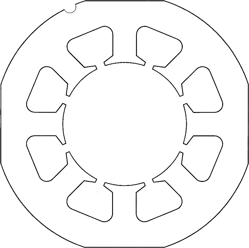
[0023] The motor is an inner rotor motor, including a stator and a squirrel cage rotor. Stator core punching sheet such as figure 1 It is square and rounded, with 8 slots with uniform opening and flat bottom (it can also be heterosexual slots, closed slots and round bottom slots), 4 of the 8 teeth are located on the symmetry axis of the 4 straight line segments, and the other 4 teeth are located on the 4 corner arcs The axis of symmetry of the segment, each tooth is wound around a coil element 6 with an insulating frame.

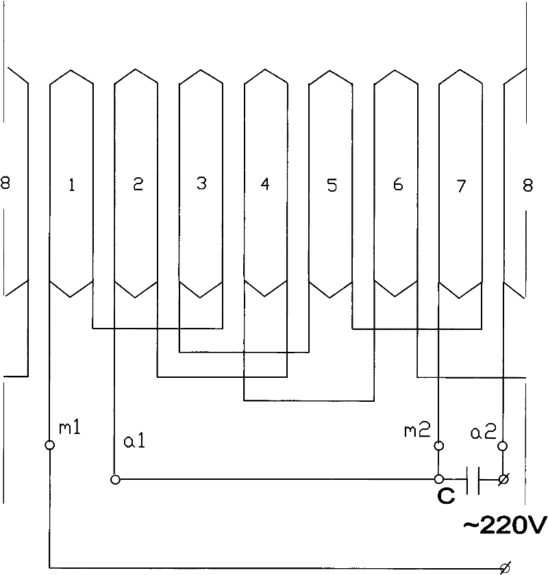
[0024] Winding construction and wiring such as figure 2 . The main phase winding connected to terminals m1 and m2 is formed by the symmetry axis located on the straight line section of iron core 5 punching piece 4 (see figure 1 ) serial numbers are 1, 3,...


PUM


Abstract

The invention relates to a low-power single-phase condenser motor, which comprises a stator core, a main phase winding, a sub-phase winding and a condenser, wherein the space electrical angle difference between the main phase winding and the sub-phase winding which are arranged on the stator core is 90 degrees; and the sub-phase winding is connected with the condenser in parallel and then is connected with the main phase winding in series to be connected to a power supply. A method for adjusting capacitance and turn number of the motor comprises the following steps: 1) wire embedding is carried out on the stator core, a rotor is used for manufacturing a two-phase winding motor prototype, the space electrical angle difference of two-phase windings which are arranged on the stator core is 90 degrees, the motor is operated symmetrically at a rated operating point, the effective turn number of the one-phase winding is Wm, the voltage of the connected power supply is Um, and the conductance g and the electrical susceptance b of the phase loop at the time are measured; and 2) the effective turn number Wm' of the main phase winding, the effective turn number Wa' of the sub-phase winding, and the capacitance C' are regulated to be as following formulas: Wm'=Wm*UN / (Um(1+(g / b)<2>)<0.5>); Wa'=Wm* (g / b)*UN / (Um(1+(g / b)<2>)<0.5>); C'=(b+b<3> / g<2>) / (2Pi*f*UN<2> / Um<2>(1+(g / b)<2>))); and in the formulas, the UN refers to the rated voltage of the motor, and the f refers to the rated frequency of the motor. Compared with the traditional technology, in the design, the winding process is improved, the computational workload is reduced, and better performance is achieved.

Description

technical field [0001] The invention relates to a small-power single-phase capacitor motor and a method for adjusting its capacitance and turns. In the International Patent Classification Table, the classification belongs to H02K3 / 28, H02K17 / 08 or H02K19 / 04. Background technique [0002] The single-phase capacitor motor of the traditional technology arranges the main phase winding and the secondary phase winding according to the specified space angle difference in the stator core and connects the secondary phase winding in parallel with the main phase winding to the power supply after the capacitor is connected in series (parallel capacitor motor for short). The inductance characteristic of the phase winding makes the main phase winding current lag behind the power supply voltage, and the characteristics of the secondary phase winding series capacitor make the secondary phase winding current lead the power supply voltage, thus leading the main phase winding current, matching ...

Claims


Application Information

Patent Timeline
IPC IPC(8): H02K17/08H02K3/28
Inventor 区长钊
Owner 叶露微
Learn More