Method for plating thin film on inner wall of slender pipeline

A pipeline, slender technology, applied in the field of vacuum coating, can solve the problems such as the inability to realize vacuum coating technology, and achieve the effects of good uniformity, strong process controllability and simple coating method

Inactive Publication Date: 2012-02-01
NO 510 INST THE FIFTH RES INST OFCHINA AEROSPAE SCI & TECH
View PDF5 Cites 4 Cited by
  • Summary
  • Abstract
  • Description
  • Claims
  • Application Information

AI Technical Summary

Problems solved by technology

[0003] The purpose of the present invention is to address the problems existing in the prior art and provide a method for coating thin films on the inner wall of slender pipes to solve the technical problem that the existing vacuum coating technology cannot meet this requirement

Method used


Image

  • Method for plating thin film on inner wall of slender pipeline
  • Method for plating thin film on inner wall of slender pipeline

Examples


Embodiment 1

[0022] Example 1: Take the reaction of trimethylaluminum and water vapor to generate aluminum oxide as an example.

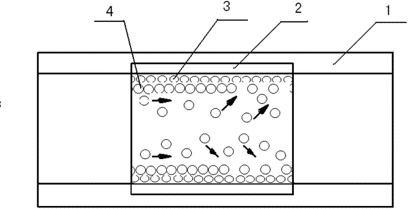
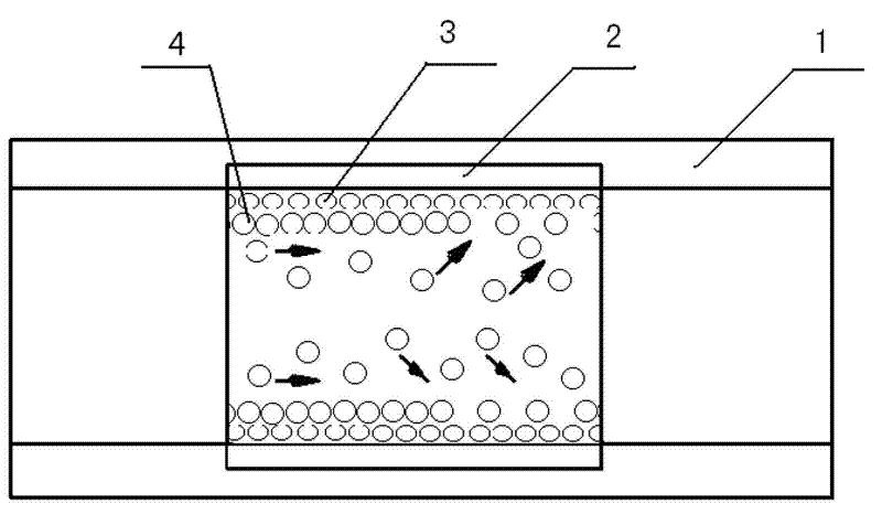
[0023] (1) Place the slender pipe to be coated in the reaction chamber (the inner wall of the reaction chamber should match the outer wall of the pipe, it is best to embed the slender pipe into the inner wall of the reaction chamber so that the inner wall of the pipe and the inner wall of the reaction chamber on the same side. See attached figure 1 , where 1 is the reaction chamber, 2 is the pipeline, 3 is the reaction precursor A, 4 is the reaction precursor B), and the reaction chamber is evacuated to 1×10 -3 Pa.

[0024] (2) Inject gas-phase reaction precursor A trimethylaluminum (TMA) into the reaction chamber in a pulse form, with a flow rate of 15 sccm and a duration of 5 s, to form a single adsorption layer by chemical adsorption on the inner surface of the pipe to be coated.

[0025] (3) Argon (Ar) gas is introduced into the reaction chamber at a flow ...

Embodiment 2

[0029] Example 2: Take the reaction of trimethylaluminum and hydrogen to generate aluminum as an example.

[0030] (1) Place the pipe to be coated in the reaction chamber (the way the pipe is placed in the reaction chamber is copper example 1), and evacuate the reaction chamber to 2×10 -3 Pa.

[0031] (2) Inject the first gas-phase reaction precursor A trimethylaluminum (TMA) into the reaction chamber in pulse form, with a flow rate of 18 sccm and a duration of 6 s, to form a single adsorption layer by chemical adsorption on the inner surface of the pipe to be coated;

[0032] (3) Argon (Ar) gas was introduced into the reaction chamber at a flow rate of 25 sccm for 15 s to remove the excess unadsorbed precursor trimethylaluminum.

[0033] (4) The second gas-phase reaction precursor B hydrogen (H 2 ), the flow rate is 15sccm, and the duration is 8s. It reacts with the precursor A trimethylaluminum (TMA) to form a monoatomic layer on the inner surface of the pipe to be coated;...

Embodiment 3

[0036] Embodiment 3: Take the reaction of titanium tetrachloride and ammonia gas to generate titanium nitride as an example.

[0037] (1) Place the pipe to be coated in the reaction chamber (the way the pipe is placed in the reaction chamber is copper example 1), and evacuate the reaction chamber to 1×10 -3 Pa.

[0038] (2) Inject the first gas phase reaction precursor A titanium tetrachloride (TiCl 4 ), the flow rate is 20sccm, and the duration is 5s. A single adsorption layer is formed by chemical adsorption on the inner surface of the pipe to be coated.

[0039] (3) Argon gas (Ar) was introduced into the reaction chamber at a flow rate of 20 sccm for 10 s to remove the excess unadsorbed precursor A titanium tetrachloride.

[0040] (4) Inject the second gas-phase reaction precursor B ammonia (NH 3 ), and react with the precursor A titanium tetrachloride adsorbed on the inner wall of the pipe to form a monoatomic layer of titanium nitride on the inner surface of the pipe t...


PUM


Abstract

The invention discloses a method for plating a thin film on an inner wall of a slender pipeline, belonging to the technical field of vacuum film plating. The method comprises the steps of: putting a pipeline to be plated with a film in a reaction chamber, alternatively introducing a gaseous phase precursor to a reactor in a pulse form, wherein the first precursor reaches to the inside of the pipeline and is chemically adsorbed on the inner wall of the pipeline to form a single adsorption layer; introducing a second precursor to react with the first precursor so as to generate a thin film with a single atom layer on the inner wall of the pipeline; cleaning the reactor through inert gas between every two precursor pulses, and repeating the adsorption and reaction processes to generate the thin film layer by layer. The method is used for plating the thin film on the inner wall of the slender pipeline in a gas adsorption and reaction combination manner to solve the problem that the thin film cannot be plated on the inner wall of the slender pipeline in a vacuum film plating method currently; and the method can be used for plating such thin film materials as metal, oxide, nitride, sulfide and fluoride, and the like so as to meet different demands.

Description

technical field [0001] The invention belongs to the technical field of vacuum coating, and relates to a method for coating various thin films on the inner wall of a pipeline, which can coat various thin film materials such as metals, oxides, nitrides, sulfides, and fluorides on the surfaces of different materials. Background technique [0002] After more than 100 years of development, thin film technology has been relatively perfect and mature, and has developed into a technical system including physical vapor deposition, chemical vapor deposition and other wet thin film preparation technologies. However, with the development of technical requirements, traditional thin-film technology still cannot meet some special requirements. For example, the existing various vacuum coating technologies can generally only coat thin films on planes or curved surfaces with less complicated shapes, and cannot achieve coating on the inner wall of pipes, especially on the inner walls of slende...

Claims


Application Information

Patent Timeline
Patent Type & Authority Applications(China)
IPC IPC(8): C23C16/44C23C16/20C23C16/40C23C16/34
Inventor 熊玉卿任妮王多书王济洲冯煜东刘恒马占吉
Owner NO 510 INST THE FIFTH RES INST OFCHINA AEROSPAE SCI & TECH
Why Eureka
Try Eureka