Novel intelligent pneumatic automatic structure pattern machine

A pattern machine, a new type of technology, applied in floral stitch sewing machines, cloth press mechanisms, sewing machine components, etc., can solve problems such as the inability to freely adjust the pressure of the presser foot, transmission failures of mechanical parts, and inconvenient movement of equipment. To achieve the effect of diversified functions, smooth and smooth movement, and low noise

Inactive Publication Date: 2012-02-01
麻佰林
View PDF4 Cites 2 Cited by
  • Summary
  • Abstract
  • Description
  • Claims
  • Application Information

AI Technical Summary

Problems solved by technology

[0002] The driving parts and the presser foot frame structure of the prior art pattern machine are V-belt pulley transmission and the traditional structure of the electromagnet. The traditional structure of the electromagnet is braked by the electromagnetic valve and moves up and down under the action of the tension spring. The structure is complex and there are many transmission structures. , prone to transmission mechanical failures, inconvenient movement of equipment, high noise, transmission failures in mechanical parts, and inability to freely adjust the pressure of the presser foot

Method used


Image

  • Novel intelligent pneumatic automatic structure pattern machine
  • Novel intelligent pneumatic automatic structure pattern machine
  • Novel intelligent pneumatic automatic structure pattern machine

Examples


Embodiment Construction

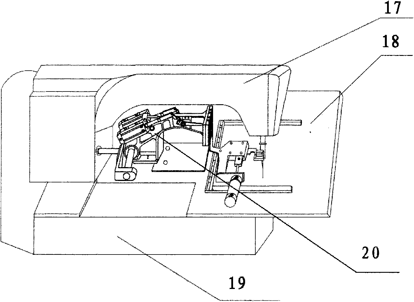
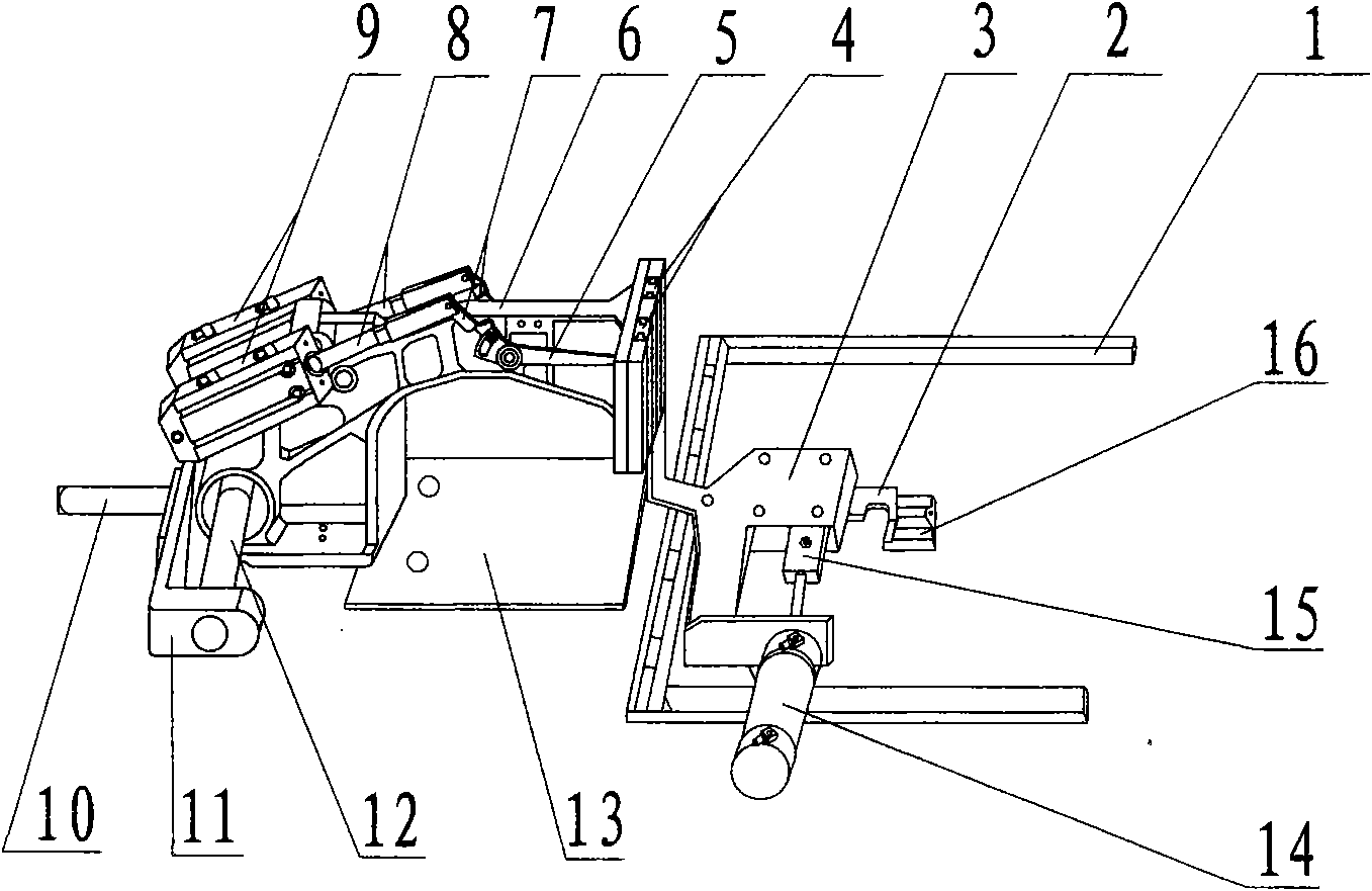
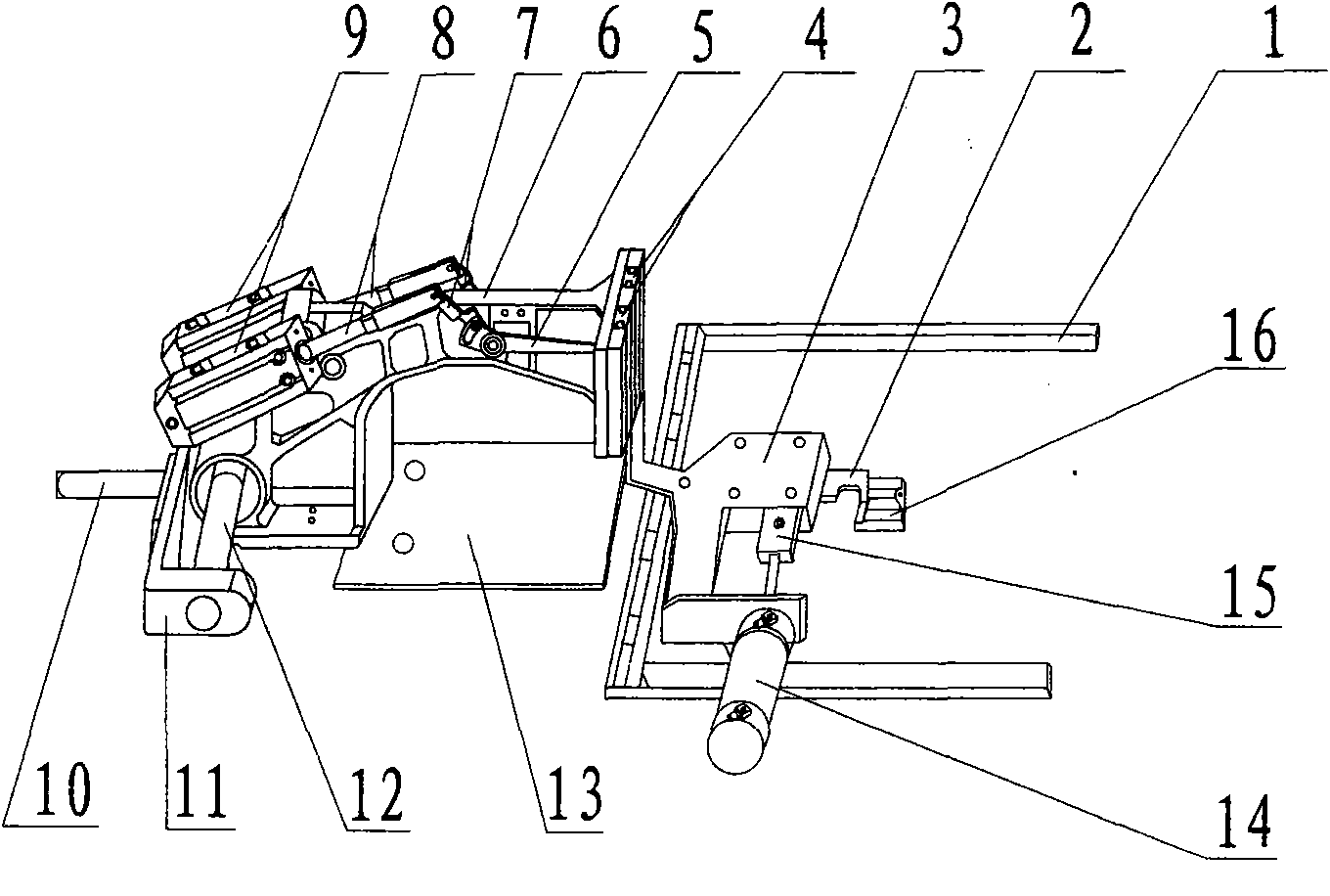
[0010] according to figure 1 , 2 As shown, after the machine is powered on, cloth is placed on the table 18 of the working surface, the computer control system drives the main shaft to move, and at the same time, the cylinder 9 works to push the Y drive shaft 10 to move back and forth. In the center, the cylinder drives the movement. The material is excellent, polished and lubricated. One end is installed on the cylinder drive shaft, and the other end is connected to the X-axis bracket. It is fixed with a mounting plate and bolted tightly. At the same time, it drives the X-direction travel axis 12 to move left and right. The X-axis support is rectangular as a whole. The thickness of the two ends and the Y transmission shaft is 15 mm. Also under the presser arm, the material is excellent, polished and lubricated, the presser arm is at the back, the edge is 12mm, and the bottom 10mm is a through hole, through which the X-direction travel axis passes. The presser arm moves alon...


PUM


Abstract

The invention discloses a novel intelligent pneumatic automatic structure pattern machine, which is composed of a feeding frame, a sliding block, a presser foot lever piece, a presser foot arm, a presser foot connecting rod, a Y transmission shaft, an X-shaft bracket, a rolling-over cylinder, a rolling-over presser foot and the like. A servo motor controls an automatic line catcher mechanism flow to form a whole by a computer system control device; the automatic line catcher mechanism drives a connecting rod to brake a linkage movement lever; the linkage movement lever brakes a front-and-back sliding crank connected with the line catcher; the servo motor is connected with a main shaft by a coupler in which a helical gear is arranged; the presser foot is an X and Y-shaft bidirectional moving rolling-over presser foot structure; the X and Y-shaft bidirectional moving rolling-over presser foot structure brakes a cylinder sliding block guide rail moving kinematic pair by the computer system control device; the cylinder sliding block guide rail moving kinematic pair drives the presser foot connecting rod to transmit by the cylinder; and the presser foot connecting rod transmits to brake a rolling-over transmission gear. The novel intelligent pneumatic automatic structure pattern machine slides in a sliding rail mode and has few faults, and the function of the rolling-over presser foot is diversified.

Description

Technical field: [0001] The invention relates to a special pattern sewing machine, in particular to a novel intelligent pneumatic automatic structure pattern machine with an automatic thread grasping structure. Background technique: [0002] The driving parts and the presser foot frame structure of the prior art pattern machine are V-belt pulley transmission and the traditional structure of the electromagnet. The traditional structure of the electromagnet is braked by the electromagnetic valve and moves up and down under the action of the tension spring. The structure is complex and there are many transmission structures. , It is prone to transmission mechanical failure, the movement of the equipment is inconvenient, the noise is large, there are transmission failures in mechanical parts, and the pressure of the presser foot cannot be adjusted freely. Invention content: [0003] Aiming at the deficiencies of the prior art, the present invention provides a new type of intel...

Claims


Application Information

Patent Timeline
Patent Type & Authority Applications(China)
IPC IPC(8): D05B9/00D05B19/12D05B29/02
Inventor 麻佰林
Owner 麻佰林
Why Eureka
Try Eureka