Method for measuring micro-impulse based on multi-beam laser heterodyne second harmonic method and torsion pendulum method
A laser heterodyne, second harmonic technology, applied in force/torque/work measuring instruments, measuring devices, instruments, etc., can solve the problem of slow signal processing operation speed, low measurement accuracy, poor laser difference frequency signal collection effect, etc. question
- Summary
- Abstract
- Description
- Claims
- Application Information
AI Technical Summary
Problems solved by technology
Method used
Image
Examples
specific Embodiment approach 1
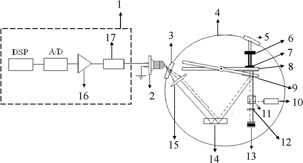
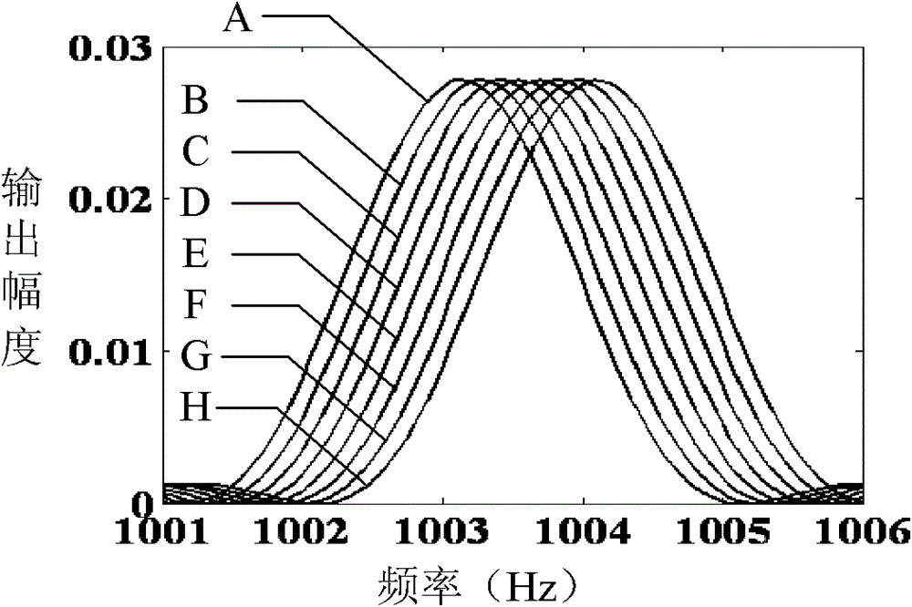
[0064] Specific implementation mode one, combination figure 1 with figure 2 In this specific embodiment, the method for measuring the micro-impulse of the second harmonic of a multi-beam laser heterodyne method based on the torsion pendulum method is implemented by adopting a system of measuring the micro-impulse of the second harmonic of a multi-beam laser heterodyne method based on the torsion pendulum method. The system includes H 0 Solid-state laser 10, torsion pendulum system, quarter wave plate 12, galvanometer 13, polarization beam splitter PBS11, converging lens 15, pulse laser 6, plane standard mirror 14, photodetector 2 and digital signal processing system 1;
[0065] Where the H 0 The solid-state laser 10, the torsion pendulum system, the quarter wave plate 12, the galvanometer 13, the polarization beam splitter PBS11, the convergent lens 15 and the plane standard mirror 14 are located in the vacuum chamber 4, which has a vacuum window 3, so The torsion pendulum system...
specific Embodiment approach 2
[0124] Specific embodiment two, the difference between this specific embodiment and the method for measuring micro impulse based on the torsion pendulum method for the second-harmonic multi-beam laser heterodyne method described in the first embodiment is that the multi-beam laser heterodyne second-order method based on the torsion pendulum method In the harmonic measurement micro-impulse system, the digital signal processing system 1 is composed of a filter 17, a preamplifier 16, an analog-to-digital converter A / D and a digital signal processing controller DSP. The filter 17 outputs the photodetector 2 The signal is filtered and sent to the preamplifier 16. The preamplifier 16 amplifies the received signal and sends it to the analog-to-digital converter A / D. The analog-to-digital converter A / D converts the received analog signal into a digital signal Send to the digital signal processing controller DSP, the FFT algorithm is solidified in the digital signal processing controller...
PUM
 Abstract
Description
Claims
Application Information
 - R&D
- Intellectual Property
- Life Sciences
- Materials
- Tech Scout
- Unparalleled Data Quality
- Higher Quality Content
- 60% Fewer Hallucinations
Browse by: Latest US Patents, China's latest patents, Technical Efficacy Thesaurus, Application Domain, Technology Topic, Popular Technical Reports.
© 2025 PatSnap. All rights reserved.Legal|Privacy policy|Modern Slavery Act Transparency Statement|Sitemap|About US| Contact US: help@patsnap.com


