
Machine tool motion dynamic graphic simulation system using service filed bus to communicate

A fieldbus and machine tool technology, applied in the field of machine tool motion dynamic graphics simulation system, can solve the problems of simulation display occupying the operation display interface, virtual simulation system does not have universality, and takes up the running time of large computers, etc., so as to reduce the dynamic graphics simulation operation time, reduce software development costs, and improve system reliability

Inactive Publication Date: 2012-02-01
BEIHANG UNIV
View PDF5 Cites 4 Cited by
  • Summary
  • Abstract
  • Description
  • Claims
  • Application Information

AI Technical Summary

Problems solved by technology

[0003] This kind of virtual simulation system has the following disadvantages: 1. The operation of the simulation software takes up a lot of computer running time, which reduces the performance of the CNC system; 2. The simulation display occupies the operation display interface, which sometimes affects the operation of the machine tool; 3. The virtual simulation system does not have general nature, cannot run in different CNC systems

Method used


Image

  • Machine tool motion dynamic graphic simulation system using service filed bus to communicate
  • Machine tool motion dynamic graphic simulation system using service filed bus to communicate
  • Machine tool motion dynamic graphic simulation system using service filed bus to communicate

Examples


Embodiment Construction

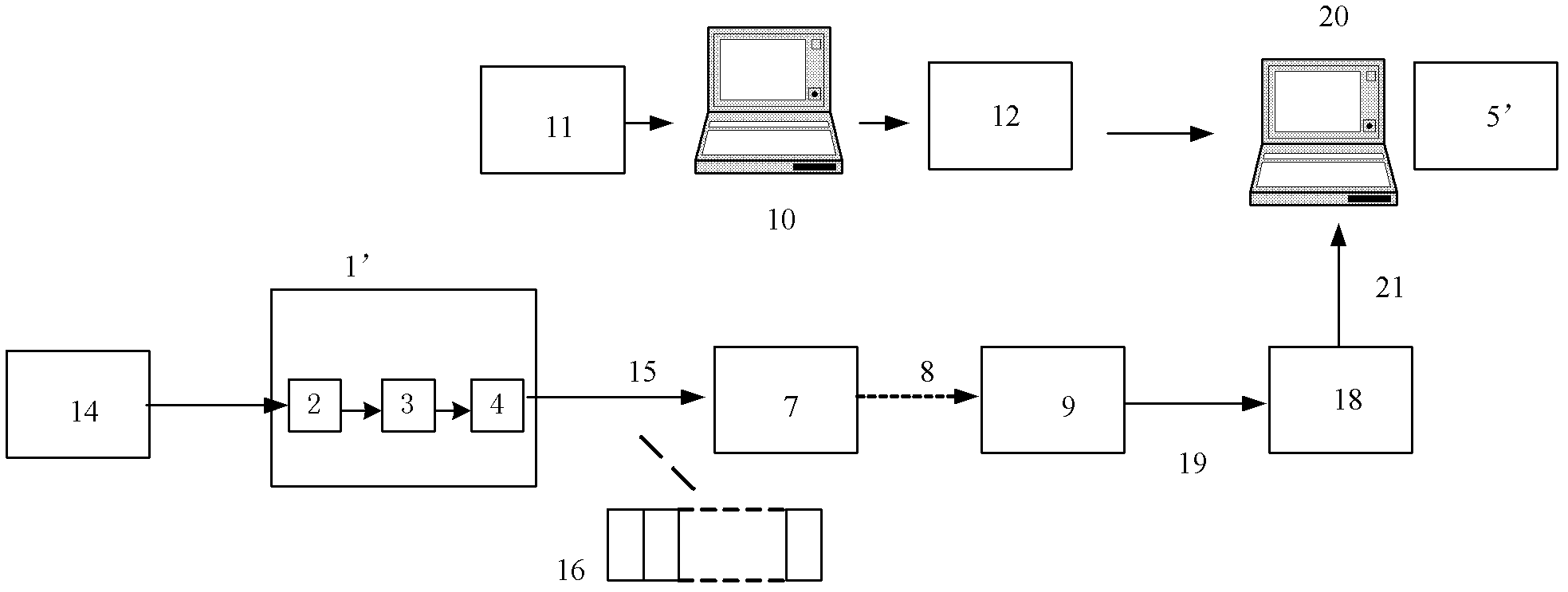
[0031] The invention is a numerical control machine tool motion graphics simulation device and software, which is composed of a servo field bus receiver and a matching computer program. The working principle is as follows figure 2 Shown. The present invention is a dynamic graphics simulation system for machine tool movement, which includes a numerical control system 1', a bus cable, a servo device 7, a bus receiver 18, a CAD machine tool modeling system 10, and a distributed simulation system 5'.

[0032] The numerical control system 1'includes: a decoder module 2, an interpolator module 3, and a field bus interface 4 of a servo device.

[0033] The CAD machine tool modeling system 10 provides the machine tool layout structure and component modeling data 12 for the dynamic graphics simulation computer 20.

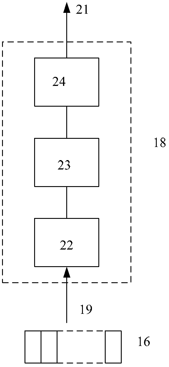
[0034] The hardware of the bus receiver 18 includes a field bus receiver interface 22, an FPGA receiving and forwarding controller 23, an Ethernet interface 24, and auxiliary cir...


PUM


Abstract

The invention discloses a construction method of a machine tool motion dynamic graphic simulation system and the machine tool motion dynamic graphic simulation system established on the method. The simulation system comprises a numerical control system, a servo device, a field bus, a bus data receiver, a simulation PC (Personal Computer) and a CAD (Computer Aided Design) modeling system. A machine tool layout structure and part modeling data which are provided by the CAD system are used by the PC; when the numerical control operates, a data frame is transmitted by the servo field bus during each cycle; a position instruction data frame is received by the simulation system through the bus data receiver and is transmitted to a simulation computer through Ethernet; and the simulation system can be used for generating three-dimensional virtual motion of a machine tool part according to the machine tool modeling data and each servo position. By adopting the construction method of the machine tool motion dynamic graphic simulation system, a software structure of the numerical control system is simplified and the simulation and operation time of the numerical control system is reduced; and a general numerical control machine tool motion simulation system is formed without occupying a system operation display interface, and thus development expense of software is reduced.

Description

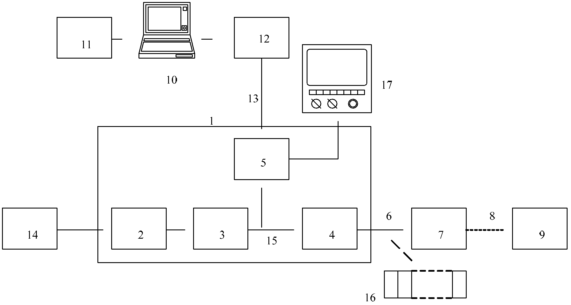
Technical field [0001] The invention relates to a machine tool motion dynamic graphic simulation system using servo field bus communication, which belongs to the field of industrial automation control. technical background [0002] The advanced CNC machine tool control system has the function of dynamic graphic simulation of machine tool movement. When the CNC machining program is running, the machine tool structure and component movement can be displayed on the CNC machine operation display, which is used for the inspection, modification and optimization of the CNC machining program, and improves the performance of the CNC machine tool. Use efficiency and convenience. The current dynamic graphics simulation system of CNC machine tool motion is such as figure 1 As shown, the numerical control system 1 includes a decoder module 2, an interpolator module 3, a servo device field bus interface 4, and an integrated simulation system 5. The field bus interface 4 of the servo device is...

Claims


Application Information

Patent Timeline
Patent Type & Authority Applications(China)
IPC IPC(8): G05B17/02
Inventor 郇极肖文磊
Owner BEIHANG UNIV
Learn More