Magnetic flowmeter with coil ground path detection

一种磁流量计、线圈的技术,应用在测量流量/质量流量、测试/校准体积流量、测量装置等方向,能够解决线圈驱动信号不能检测、不精确流量测量、EMF减小等问题

Active Publication Date: 2012-02-01
MICRO MOTION INC
View PDF4 Cites 6 Cited by
  • Summary
  • Abstract
  • Description
  • Claims
  • Application Information

AI Technical Summary

Problems solved by technology

This results in a reduction in the applied EMF, and a corresponding reduction in the output from the sensing electrodes
This can result in inaccurate flow measurements
[0004] Loss of coil drive signal typically cannot be detected by simply measuring coil drive current

Method used


Image

  • Magnetic flowmeter with coil ground path detection
  • Magnetic flowmeter with coil ground path detection
  • Magnetic flowmeter with coil ground path detection

Examples


Embodiment Construction

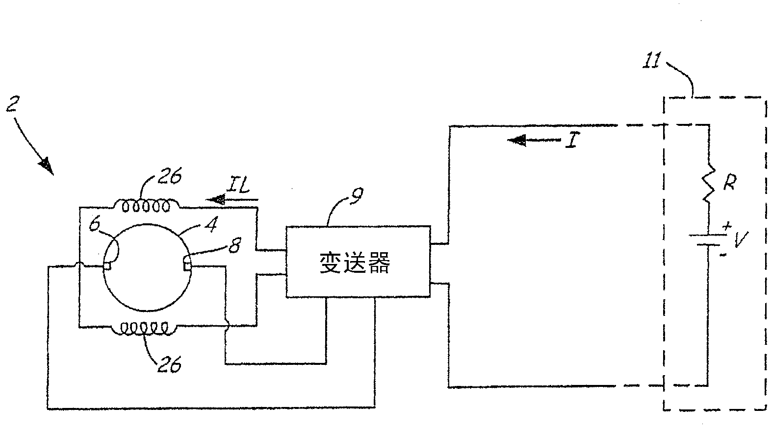
[0012] exist figure 1 , the magnetic flowmeter system 2 is connected to a two-wire communication 4-20mA loop carrying current I and to an AC power line (not shown). Flow tube 4 carries the fluid flow. Transmitter 9 provides coil drive current I to coil 26 adjacent to flow tube 4 L , the coil 26 generates a magnetic field in the fluid. Electrodes 6, 8 are mounted in the flow tube 4 along lines perpendicular to the magnetic field in the fluid for sensing EMF induced by the fluid flow. The transmitter 9 senses the EMF between the electrodes 6, 8 and controls a DC output current I representative of the sensed EMF, which is proportional to the fluid flow. Transmitter 9 sends current I to remote receiving station 11 on a 4-20mA current loop. Transmitter 9 may also send flow output in digital form using HART digital protocol, Fieldbus protocol, wireless protocol, or other technologies.

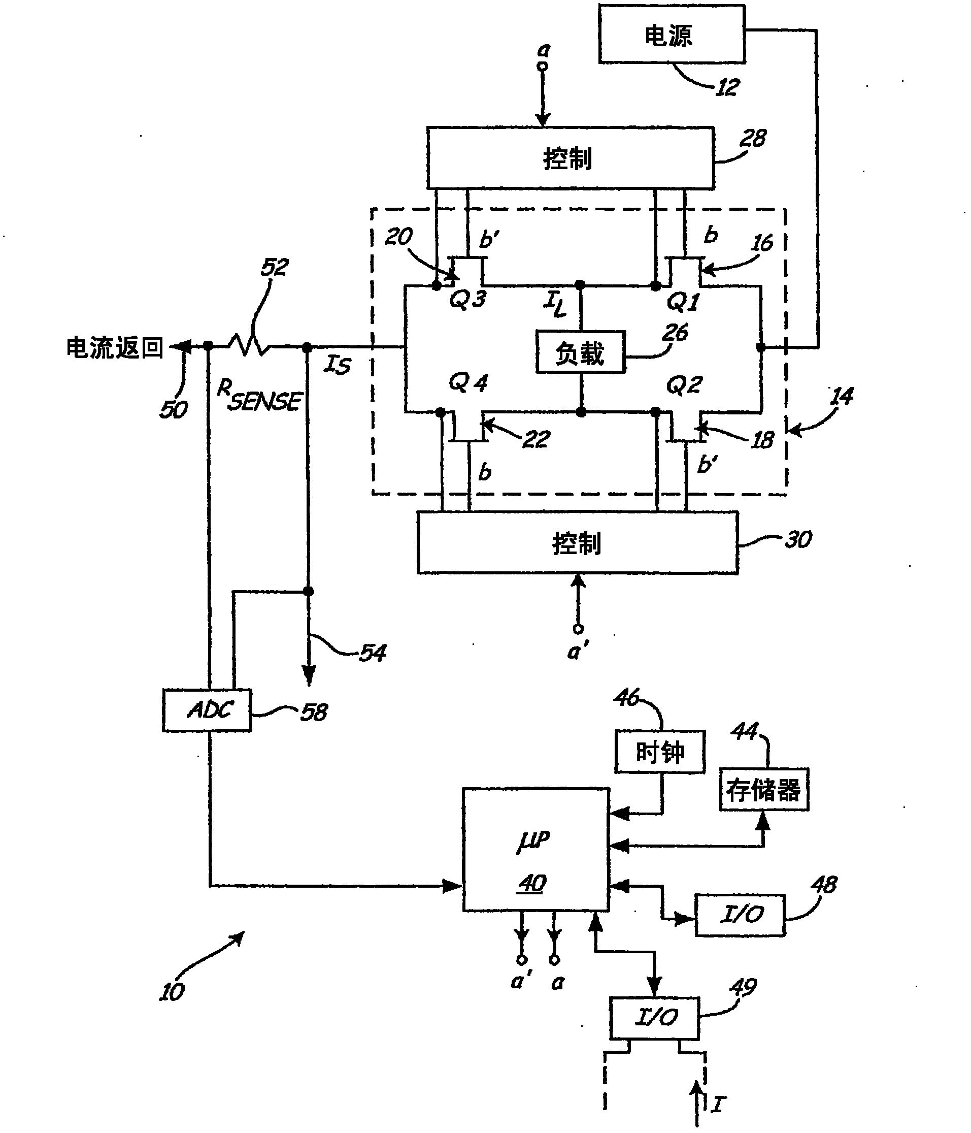
[0013] figure 2 The driver circuit 10 in the transmitter 9 is shown. The H-bridge flow tu...


PUM


Abstract

A magnetic flow meter (2) includes a flowtube (4) arranged to receive a flow of process fluid and a coil (26) proximate the flowtube arranged to apply a magnetic field to the process fluid. A sense electrode (68) is arranged to sense a voltage potential in the flowtube in response to the applied magnetic field. The sensed voltage is indicative of flow rate of process fluid through the flowtube. Diagnostic (40) circuitry provides an output related to an electrical path between the coil and electrical ground.

Description

Background technique [0001] The present invention relates to magnetic flowmeters. More specifically, the present invention relates to magnetic flow meters employing coil ground path detection. [0002] Magnetic flowmeters measure the volumetric flow rate of conductive fluids by sensing the velocity of the fluid flowing through a magnetic field. A magnetic flowmeter system typically includes a flow tube assembly and a transmitter assembly. A flow tube assembly is installed vertically or horizontally in a process pipeline and includes a pipe section, a coil section, and electrodes. The coils are located on opposite sides of the pipe cross-section. A coil powered by coil drive current from the transmitter generates a magnetic field along the cross-section of the pipe. The two electrodes straddle each other across the pipe along a line perpendicular to the magnetic field. Fluid flowing through pipes is electrically conductive. As the conductor moves through the magnetic fiel...

Claims


Application Information

Patent Timeline
Patent Type & Authority Applications(China)
IPC IPC(8): G01F1/60G01F25/00
CPCG01F25/0007G01F1/586G01F25/10
Inventor 斯科特·R·弗斯罗伯特·K·舒尔兹
Owner MICRO MOTION INC
Why Eureka
Try Eureka