Injection pump and suction method thereof

A jet pump and flange technology, applied in the field of jet pumps, can solve problems such as increased cost of use, inability to pump solids, suction blockage, etc., and achieve the effects of high suction, wide range of use, and reliable work

Inactive Publication Date: 2012-02-08
芜湖天远生物科技有限公司
View PDF1 Cites 15 Cited by
  • Summary
  • Abstract
  • Description
  • Claims
  • Application Information

AI Technical Summary

Problems solved by technology

[0003] At present, the usual jet pumps use water and steam as the main medium, which not only causes waste of resources, but also increases the cost of use
Moreover, the current jet pump can only pump gas and liquid, but cannot pump solids, because solids will cause suction blockage

Method used


Image

  • Injection pump and suction method thereof
  • Injection pump and suction method thereof
  • Injection pump and suction method thereof

Examples


Embodiment Construction

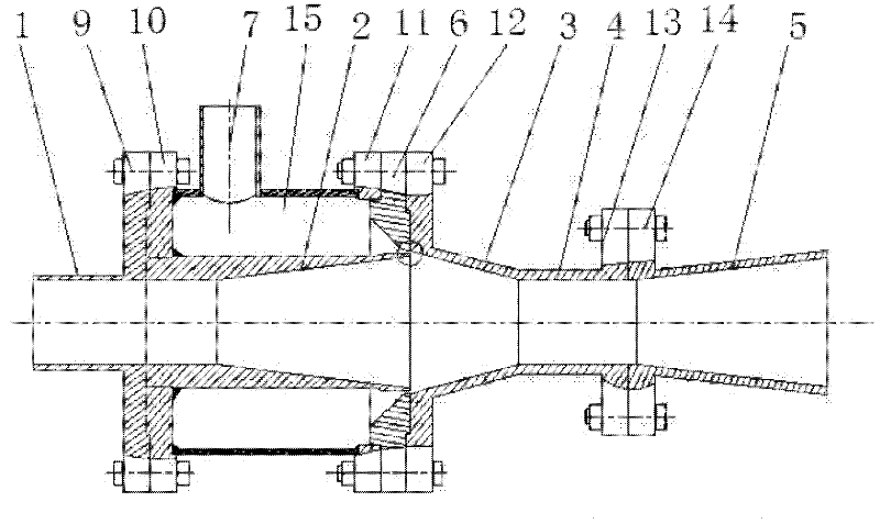
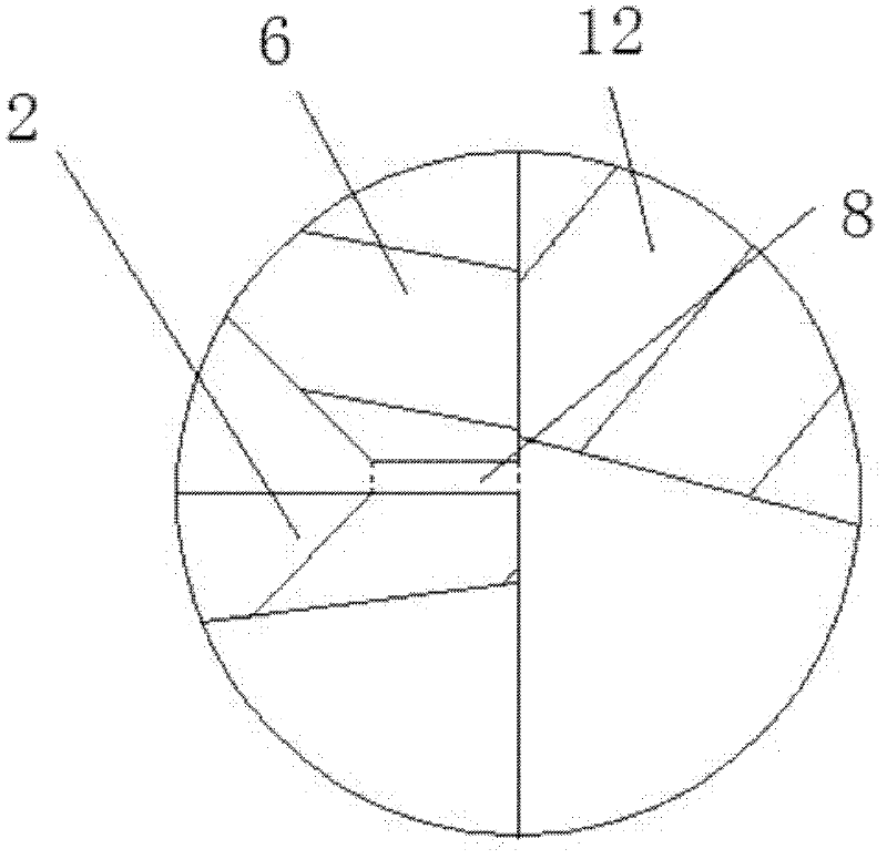
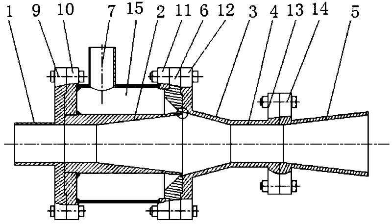
[0021] Such as Figure 1 ~ Figure 2 A jet pump shown includes a suction pipe 1, a nozzle 2, a throat inlet section 3, a throat 4, a diffusion pipe 5, and an annular spout 6, and one end of the inner chamber of the nozzle 2 communicates with the suction pipe 1 feed inlet, the other end is a discharge outlet, and the aperture of the discharge outlet is greater than the aperture of the feed inlet, and one end of the nozzle 2 is cylindrical, and the other end is a trumpet shape. The discharge port of the nozzle 2 inner cavity is connected with the throat inlet section 3, the throat pipe 4, and the diffuser pipe 5 in sequence. The diameter of the outlet port of the diffusion tube 5 is larger than that of the inlet port, and the diffusion tube 5 is bell-shaped. The outside of the nozzle 2 is provided with an annular air chamber 15, the air chamber 15 communicates with the intake pipe 7, and an annular gap 8 for ventilation is provided between the inner wall of the annular nozzle 6 ...


PUM


Abstract

The invention discloses an injection pump and a suction method thereof. The injection pump comprises a suction pipe, a nozzle, a choke inlet section, a choke, a diffusing pipe and an annular nozzle, wherein the caliber of a discharging hole of an inner cavity of the nozzle is more than that of a feeding hole of the inner cavity of the nozzle, the discharging hole of the inner cavity of the nozzle is sequentially communicated with the choke inlet section, the choke and the diffusing pipe, the caliber of the inlet end of the choke inlet section is more than that of the outlet end of the choke inlet section, the caliber of the outlet end of the diffusing pipe is more than that of the inlet end of the diffusing pipe, an annular air chamber is arranged on the outer side of the nozzle and communicated with an air inlet pipe, a ventilating annular gap is arranged between the inner wall of the annular nozzle and the nozzle, one end of the gap is communicated with the inlet end of the choke inlet section, and the other end of the gap is communicated with the air chamber. The invention has the advantages that the injection pump has high vacuum degree by completely using an air medium as power, strong self-absorption capacity, high suction stroke, no blockage and low cost, is suitable in environments with high temperature, high pressure, deep water, strong radiation, strong corrosion and the like, and can be used for sucking fluid with higher concentration and larger-particle solid materials.

Description

technical field [0001] The invention relates to the technical field of jet pumps, in particular to a jet pump. Background technique [0002] How to use compressed air as the working medium in the pump has always been a difficult problem at home and abroad. There are many reasons for this, mainly because the density of the air is too small and the use value is low. Water is incompressible, but gas is compressible, and compressed air will expand when it is released, which brings many difficulties and obstacles to the design of jet pumps that use compressed air as the working medium. Aerodynamics and fluid mechanics are also involved when the air drags the material in the movement of the pump body. When the two are mixed, it is extremely complicated, and it is difficult to calculate and form reliable theoretical data. There is no pump theory using compressed air as the working medium, and its specific theoretical basis is also lacking. [0003] At present, the usual jet pump...

Claims


Application Information

Patent Timeline
Patent Type & Authority Applications(China)
IPC IPC(8): F04F5/24F04F5/44
Inventor 冀民民姚云山
Owner 芜湖天远生物科技有限公司
Why Eureka
Try Eureka