Condensate water recovery device

A technology for recycling device and condensate water, which is applied in the directions of supplementary water supply, preheating, steam generation, etc., can solve the problems of large temperature drop of condensate water, affecting energy saving effect, unfavorable energy saving and environmental protection, etc., achieving less temperature loss, reducing pipeline corrosion, high temperature effect

Inactive Publication Date: 2012-02-08
王素侠
View PDF0 Cites 2 Cited by
  • Summary
  • Abstract
  • Description
  • Claims
  • Application Information

AI Technical Summary

Problems solved by technology

[0003] The object of the present invention is: aiming at the above-mentioned defects existing in the recovery process of the existing boiler condensed water, the present invention provides a condensed water recovery device, which overc

Method used


Image

  • Condensate water recovery device
  • Condensate water recovery device

Examples


Embodiment Construction

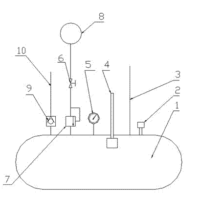
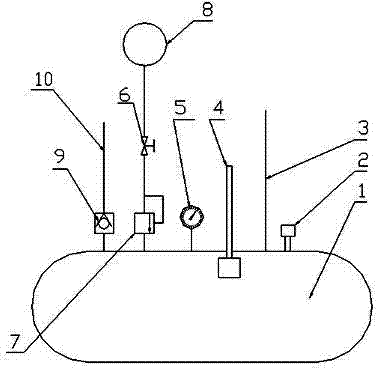
[0009] In the figure, the condensed water recovery device includes a water storage tank 1, a safety valve 2, an outlet pipe 3, a water level sensor 4, a pressure gauge 5, a stop valve 6, a pressure reducing valve 7, an air compressor 8, a one-way valve 9, The water inlet pipe 10, the water storage tank 1 of the present invention is an airtight container, and is also a place for temporary storage and transfer of condensed water. A safety valve 2, an outlet pipe 3, a water level sensor 4, and a pressure gauge are fixedly installed on the water storage tank 1 5. The outlet pipe 3 is connected to the water inlet of the boiler, the air compressor 8 is connected to the inside of the water storage tank 1 through the stop valve 6 and the pressure reducing valve 7, and the water inlet pipe 10 is connected to the inside of the gas storage tank 1 through the one-way valve 9 , The water inlet pipe 1 is connected to the condensed water outlet end of the condenser. When the water lev...


PUM


Abstract

The invention discloses a condensate water recovery device. The condensate water recovery device comprises a water storage tank on which a safety valve, a water outlet pipe, a water level sensor and a pressure gauge are orderly arranged, the water storage tank is connected with a water inlet of a boiler, an air compressor is connected with the inside of the water storage tank through a stop valve and a reducing valve, a water inlet pipe is communicated with the inside of an air storage tank through a one-way valve, and the water inlet pipe is connected with a condensate water outlet end of a condenser. For the condensate water recovery device, underground pipelines and underground water reservoirs paved in a condensate water recovery process are not needed, so that the defects of leakage caused by corrosion and damage on the pipelines and direct influence on the quality of the condensate water are reduced, and simultaneously, heat loss of the condensate water is less and temperature of the condensate water is higher, which is beneficial for energy saving and environmental protection.

Description

technical field [0001] The invention relates to an environmental protection technology, in particular to a condensed water recovery device. Background technique [0002] In some industries, boiler steam is often used as the heat source, and the heat is sent out through the radiator to dry the products. The condensed water generated during the heat exchange process is discharged from the drain, and the condensed water is sent to the water collection station through underground pipes, and then The condensed water is sent to the boiler by an electric pump for recycling. Because the pipeline has been mixed underground for a long time, the corrosion is serious, the pipeline is damaged and the liquid leaks, which directly affects the quality of condensed water. In addition, the hot water return pipeline intersects with the sewer underground, and part of the pipeline is submerged in the sewer, which greatly reduces the temperature of the condensed water, affects the energy saving...

Claims


Application Information

Patent Timeline
IPC IPC(8): F22D11/06
Inventor 王素侠
Owner 王素侠
Why Eureka
Try Eureka